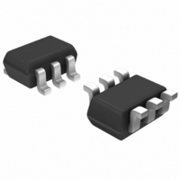
LMN400E01-7 Diodes Inc, LMN400E01-7 Datasheet - Page 2

LMN400E01-7
Manufacturer Part Number
LMN400E01-7
Description
MCU LOAD SWITCH 400MA SOT-363
Manufacturer
Diodes Inc
Datasheet
1.LMN400E01-7.pdf
(8 pages)
Specifications of LMN400E01-7
Transistor Type
PNP Pre-Biased, N-Channel Pre-Biased
Applications
Load Switch
Voltage - Rated
50V PNP, 60V N-Channel
Current Rating
400mA PNP, 115mA
Mounting Type
Surface Mount
Package / Case
6-TSSOP, SC-88, SOT-363
Lead Free Status / RoHS Status
Lead free / RoHS Compliant
Other names
LMN400E01DITR
LMN400E01TR
LMN400E01TR
LMN400E01TR
LMN400E01TR
Maximum Ratings:
Sub-Component Device: Pre-Biased PNP Transistor (Q1)
Sub-Component Device:
ESD Protected N-Channel MOSFET (Q2)
Electrical Characteristics: Pre-Biased PNP Transistor (Q1)
Collector-Base Voltage
Collector-Emitter Voltage
Supply Voltage
Input Voltage
Output Current
Drain-Source Voltage
Drain Gate Voltage (R
Gate-Source Voltage
Drain Current (Page 1: Note 3)
Continuous Source Current
OFF CHARACTERISTICS (Note 4)
Collector-Base Cut Off Current
Collector-Emitter Cut Off Current
Emitter-Base Cut Off Current
Collector-Base Breakdown Voltage
Collector-Emitter Breakdown Voltage
Input Off Voltage
Output Voltage
Ouput Current (leakage current same as I
ON CHARACTERISTICS (Note 4)
Collector-Emitter Saturation Voltage
Equivalent on-resistance
DC Current Gain
Input On Voltage
Output Voltage (Equivalent to V
Input Current
Base-Emitter Turn-on Voltage
Base-Emitter Saturation Voltage
Input Resistor (Base), +/- 30%
Pull-up Resistor (Base to Vcc supply), +/- 30%
Resistor Ratio (Input Resistor/Pullup resistor)
SMALL SIGNAL CHARACTERISTICS
Transition Frequency (Gain Bandwidth Product)
Collector capacitance, (C
Capacitance)
Notes:
DS30750 Rev. 7 - 2
4. Short duration pulse test used to minimize self-heating effect.
Characteristic
Characteristic
GS
≤ 1M Ohm)
cbo
Characteristic
-Output
CE(SAT)
Pulsed (tp <10 uS, Duty Cycle <1%)
)
CEO)
Continuous (V
Pulsed (tp<50 uS)
V
V
R
Symbol
V
V
V
V
I
V
R1/R2
(BR)CBO
(BR)CEO
V
CE(SAT)
O(OFF)
CE(SAT)
BE(SAT)
I
I
I
BE(ON)
V
I(OFF)
h
O(ON)
CC
CBO
CEO
EBO
R2
R1
I(ON)
f
I
OH
FE
T
I
Continuous
gs
= 10V)
www.diodes.com
Symbol
0.154
Min
-4.9
V
V
-50
-50
70
70
36
⎯
⎯
⎯
⎯
⎯
⎯
⎯
⎯
⎯
⎯
-3
⎯
⎯
⎯
⎯
⎯
⎯
V
7
V
CBO
CEO
I
C
cc
in
@T
2 of 8
A
= 25°C unless otherwise specified
-0.55
0.22
Symbol
Typ
220
225
-1.5
-0.1
-1.2
-1.9
200
-18
10
45
20
⎯
⎯
⎯
⎯
⎯
⎯
⎯
⎯
⎯
⎯
⎯
⎯
V
V
V
DGR
GSS
DSS
I
I
D
S
1.125
0.286
-0.15
Max
-100
-500
-500
-0.3
-0.3
-0.5
-0.6
-0.3
-1.4
-2.2
-28
13
55
⎯
⎯
⎯
⎯
⎯
⎯
⎯
⎯
-1
@T
+5 to -6
Value
-400
-50
-50
-50
@T
A
= 25°C unless otherwise specified
A
MHz
= 25°C unless otherwise specified
Unit
mA
mA
KΩ
KΩ
nA
nA
nA
pF
⎯
⎯
⎯
Value
V
V
V
V
V
V
V
V
Ω
V
V
V
V
+/-20
+/-40
300
800
300
60
60
V
V
V
I
I
V
V
V
I
IC
I
I
I
V
V
V
I
V
V
I
V
f = 100MHz
V
f = 1MHz
C
C
C
C
C
C
o
C
CB
CE
EB
CE
CC
CC
CE
CE
O
/I
I
CE
CE
CB
= -200mA, I
= -10uA, I
= -2mA, I
= -10mA, I
= -400mA, I
= -500mA, I
= -400mA, I
= -50mA, I
= -5V
I
= -0.3V, I
= -50mA /-2.5mA
= -5V, I
= -50V, I
= -5V, I
= -5V, V
= -50V, V
= -5V, I
= -5V, I
= -5V, I
= -10V, I
= -10V, I
= -50V, I
Test Condition
C
B
C
C
C
C
E
B
C
B
B
E
E
E
= 0
= 0
= -100uA
= -50mA
= -400mA
= -400mA
B
= 0
I
B
B
B
B
= -0.05V, R
= -20mA
= -0.3mA
= -5mA
= 0
= -5mA,
= 0A,
= 0V
= -40mA
= 0
⎯
⎯
⎯
= -20mA
Unit
= -50mA
= -40mA
mA
© Diodes Incorporated
V
V
V
V
Unit
mA
mA
V
V
V
LMN400E01
L
= 1K


