1-206062-4 TE Connectivity, 1-206062-4 Datasheet
1-206062-4
Specifications of 1-206062-4
Available stocks


Related parts for 1-206062-4


1-206062-4 Summary of contents
Page 1
AMP Circular Connectors for Commercial Signal & Power Applications RoHS Ready ...
Page 2
... Uses existing Mini-Universal I MATE-N-LOK stamped and formed pin and socket contacts Two shell sizes—available and position configurations Need more information? Call Technical Support. They are staffed with specialists well versed in Tyco Electronics products. They can provide: Technical Support ...
Page 3
... Example of New Current Rating Format . . . . . . . . . . . . . . . . . . . . . . . . . . . . . . . . . . . . . . . . . . . . . . . . . . . . . . .9 CPC, Series 1 Cable or Panel Mount Connectors . . . . . . . . . . . . . . . . . . . . . . . . . . . . . . . . . . . . . . . . . . . . . . . . . . . .10, 11 Printed Circuit Board Mount Connectors . . . . . . . . . . . . . . . . . . . . . . . . . . . . . . . . . . . . . . . . . . . . . . .12, 13 Square Flange Receptacles with Round Posted Contacts . . . . . . . . . . . . . . . . . . . . . . . . . . . . . . . . . . . . .13 Square Flange Receptacles with Solder Cup Contacts . . . . . . . . . . . . . . . . . . . . . . . . . . . . . . . . . . . . . . .14 Feed-Thru Connectors . . . . . . . . . . . . . . . . . . . . . . . . . . . . . . . . . . . . . . . . . . . . . . . . . . . . . . . . . . . . . . . .14 Square Flange Receptacles, Right-Angle, Posted . . . . . . . . . . . . . . . . . . . . . . . . . . . . . . . . . . . . . . . .15,16 Contacts, Type III+ (including Lead Free and Enhanced High Current .17-20 Contacts, Type II ...
Page 4
... Series 3—Power Contacts Series 3 connectors accept 1 2 Type XII power contacts which can carry amps per contact. These 3 5 contacts will accommodate a wire size range Series 4—Combination 1 Size 16 and Power Contacts 2 3 Series 4 connectors accept Size 16 Multimate and 4 ...
Page 5
... Two shell sizes (8 or 11) are available, accommodating from and positions Dimensions are shown for USA: 1-800-522-6752 reference purposes only. Canada: 1-905-470-4425 Specifications subject Mexico: 52-55-1106-0800 to change ...
Page 6
... Protection Against Water Temperature Life Insulation Resistance (MIL-STD-1344, Method 3003) Humidity (MIL-STD-202, Method 103, Test Condition B) *For size 16 contacts. Size 8 contacts 25 lb. load, min. 6 Catalog 82021 Dimensions are in inches and Revised 7-07 millimeters unless otherwise specified. Values in brackets www.tycoelectronics.com are metric equivalents. ...
Page 7
... Wire Entry Seals Per IEC 60529—Pertains to degrees (for Discrete Wire I of protection provided by enclosures Applications) or Heat (IP code). Shrink Boots (for Jacketed Cable Applications). Sample Designation: Available are Various Sizes, Series 1, 5 and 6. (Where numeral value), i. Codes IP Index Letter Degree of Protection ...
Page 8
... The wire also conducts heat away from the connector. Current Rating Verification design-life (EODL) conditions. Practical current-carrying capac- Can a contact rated at 10 amps ity is not an absolute, but an carry 10 amps? application-dependent condition. Maybe yes, but probably not. New Method Simplifies Ratings ...
Page 9
... The specific rating for this I application is the product of Practical Values the base rating and the rating factor: The current-rating method 14 x 0.68 = 9.5 ampere gives designers practical values applicable to their appli- Each of the contacts can I cations. While the specified carry 9.5 ampere. ...
Page 10
... B—Optional Configuration: 4 Keys to prevent mismating of standard and reverse sex. 1 Four 4-40 threaded inserts per receptacle. Key Style “A” is the Standard 5 Locating Key arrangement. Key Style “B” is the 4 Locating Key arrangement. 10 Catalog 82021 Dimensions are in inches and Revised 7-07 millimeters unless otherwise specified ...
Page 11
... Four 4-40 threaded inserts per receptacle. Key Style “A” is the Standard 5 Locating Key arrangement. Key Style “B” is the 4 Locating Key arrangement. Keying A—Standard Configuration: 5 Keys B—Optional Configuration: 4 Keys Catalog 82021 Dimensions are in inches and Revised 7-07 millimeters unless otherwise specified ...
Page 12
... Molded-in keying in two configurations: A—Standard Configuration: 5 Keys B—Optional Configuration: 4 Keys to prevent mismating of standard and reverse sex. Note: Posts are .017 [0.43] offset from centerline of contacts. All posts must be oriented in the same plane for proper contact/post location. Other Available Posted Contacts Tyco Electronics can make ...
Page 13
... With Round Posted Contacts (Size 16), Contact Arrangement 17-16 23-37 Note: Posts are .017 [0.43] offset from centerline of contacts. All posts must be oriented in the same plane for proper Material and Finish contact/post location. Housing—Thermoplastic, 94V-0 rated, heat-stabilized, fire-resistant, self- extinguishing, black Contacts— ...
Page 14
... Contact Arrangement 17-16 Material and Finish Housing—Thermoplastic, 94V-0 rated, heat-stabilized, fire-resistant, self- extinguishing, black Contacts—Brass Notes: 1. Connector can be used for Plating— Connector Part No. 206404-1— Plated .000030 [0.00076] min. gold over Notes: .000030 [0.00076] min. nickel on entire contact Connector Part No. 206404-2— ...
Page 15
... Material and Finish Housing—Thermoplastic, 94V-0 rated, black Location Wafer—Phenolic, black Contact Posts—.000100 [0.00254] min. tin over .000100 [0.00254] min. copper Contact Body— A—.000100 [0.00254] min. tin over .000050 [0.00127] min. nickel B—.000030 [0.000762] min. gold for a length of ...
Page 16
... Housing—Thermoplastic, 94V-0 rated, .16 black [4.064] Location Wafer—Phenolic, black Contact Posts—.000100 [0.00254] min. tin over .000100 [0.00254] min. copper Contact Body— A—.000100 [0.00254] min. tin over .000050 [0.00127] min. nickel B—.000030 [0.000762] min. gold for a length of ...
Page 17
... Pin Application Tooling—Pages 76-79 Technical Documents 114-10004 Application Specification 108-10042 Product Specification ‡Single contact, free-air test current is not to be construed as contact rating current. Use only for testing. Refer to contact current carrying capability information on page 8. Strip Form Loose Piece Contact Contact No. ...
Page 18
... Overall insulation crimp diameter, including crimp barrel, must not exceed .125 [3.18]. 2 Contacts can ONLY be used in CPC, Series 1 (Arr. 23-24), Series 4 (Arr. 23-13M, 23-16M, 23-22M), and VDE connectors use with the 626 Pneumatic Tool System: remove the crimping head from the Straight Action Hand Tool (SAHT) Assembly, order SAHT Adapter Part No ...
Page 19
... To use with the 626 Pneumatic Tool System: remove the crimping head from the Straight Action Hand Tool (SAHT) Assembly, order SAHT Adapter Part No. 217201-1, Adapter Holder Part No. 356304-1 (with ratchet) or 189928-1 (without), and Power Unit Part No. 189721-1 (hand actuated) or 189722-1 (foot actuated). ...
Page 20
... Designed for AWG; but, not to exceed current limitation of contact. Note: These contacts can be used in Multimate contact cavities of all connector housings. ‡Single contact, free-air test current is not to be construed as contact rating current. Use only for testing. Refer to contact current carrying capability information on page 8. ...
Page 21
... PRO-CRIMPER II Hand Tool for field repair use only. Note: Die Set can be adapted for use with the 626 Pneumatic Tool System. †Does not use Hand Tool 91539-1 or 601967-1. ‡Single contact, free-air test current is not to be construed as contact rating current. Use only for testing. Refer to contact current carrying capability information on page 8. ...
Page 22
... Die Set requires “C” Head Adapter Part No. 318161-1; Adapter Holder Part No. 356304-1 (with ratchet) or 189928-1 (without); and Power Unit Part No. 189721-2 (hand actuated) or 189722-2 (foot actuated). †Does not use Hand Tool 91539-1 or 601967-1. ...
Page 23
... Die Set requires “C” Head Adapter Part No. 318161-1; Adapter Holder Part No. 356304-1 (with ratchet) or 189928-1 (without); and Power Unit Part No. 189721-2 (hand actuated) or 189722-2 (foot actuated). *Used with PRO-CRIMPER II Hand Tool Frame Part No. 354940-1. ...
Page 24
... Arrangement 11-4 Max. Wire Ins. Dia. = .100 [2.54] Shell Size 17 .197 .197 .000 [5] [5] .197 [5] .000 .197 [5] Arrangement 17-9 Max. Wire Ins. Dia. = .150 [3.81] Shell Size 23 ...
Page 25
... AMP Circular Connectors for Commercial Signal and Power Applications Component Dimensions, Series 1 Square Flange Receptacle ±.010 D [±0.25] ±.015 B [±0.38] Free-Hanging Receptacle ±.015 B [±0.38] ±.010 D [±0.25] Plug Thread Size (See chart) Shell Sex Size 1.070 Rev. 27.18 .420 ...
Page 26
... Four 4-40 threaded inserts per receptacle. Note: For Standard and Reverse Sex Connectors the maximum wire insulation diameter is .068 [1.73]. 26 Catalog 82021 Dimensions are in inches and Revised 7-07 millimeters unless otherwise specified. Values in brackets www.tycoelectronics.com are metric equivalents. ...
Page 27
... Size Positions gold on contact engagement area, tin on the termination area, all over .000050 [0.00127] min. nickel under- 11-9 plating B—Plated gold flash on the entire contact, tin on the termination area 17-28 Related Product Data 23-63 Contact Arrangement—Page 31 Performance Characteristics— Page 6 1 Four 4-40 threaded inserts per receptacle ...
Page 28
... AMP Circular Connectors for Commercial Signal and Power Applications Circular Plastic Connectors, Series 2 Special CPC Connectors, Square Flange Feed-Thru Receptacles (with Permanently Sealed .040 [1.02] Dia. Solid Pins) Series 2 (Pressure rated psi) B Listed plug connector part numbers are for connectors only; contacts must be ordered separately ...
Page 29
... To use with the 626 Pneumatic Tool System: remove the crimping head from the Straight Action Hand Tool (SAHT) Instruction Sheet—408-9404 Assembly, order SAHT Adapter Part No 217201-1, Adapter Holder Part No. 356304-1 (with ratchet) or 189928-1 This tool includes interchangeable (without), and Power Unit Part No. 189721-1 (hand actuated) or 189722-1 (foot actuated). ...
Page 30
... QQ-B-626 24-20 0.2-0.6 .068 Socket Body—Beryllium copper per QQ-C-530 1 Overall insulation crimp diameter, including crimp barrel, must not exceed .125 [3.18]. .000015 [0.00038] gold in the mating area over .000050 [0.00127] nickel. Socket Sleeve—Passivated stainless 2 steel per QQ-S-766 Plating pin and socket body— ...
Page 31
... Arrangement 23-57 Max. Wire Ins. Dia. = .068 [1.73] Catalog 82021 Dimensions are in inches and Revised 7-07 millimeters unless otherwise specified ...
Page 32
... M N .840 .817 .935 .800 .975 5/8-24 20.75 23.75 20.32 24.77 UNEF-2A 1.161 1.310 .800 1.349 15/16-20 29.49 33.27 20.32 UNEF-2A 34.26 1.500 1.733 .915 1.788 1-3/8-18 38.1 44.02 23.24 45.42 UNEF-2A South America: 55-11-2103-6000 Hong Kong: 852-2735-1628 Japan: 81-44-844-8013 UK: 44-208-420-8341 ...
Page 33
... Contact Arrangement—Page 35 Component Dimensions—Page 36* Accessories—Pages 38-42 Performance Characteristics— Page 6 Application Tooling—Pages 76-79 ±.010 *D [±0.25] Technical Documents—Page 80 Plug Standard Sex Connectors (Receptacles accept Type XII Male/pin contacts, Plugs accept Type XII Female/socket contacts) ...
Page 34
... Die insert Part No. 90145-1 is for crimping 14-12 AWG [2 Recommended for high current/vibration applications where fretting corrosion is a problem. Die Set requires “C” Head Adapter Part No. 318161-1; Adapter Holder Part No. 356304-1 (with ratchet) or 189928-1 (without); and Power Unit 7 Part No. 189721-2 (hand actuated) or 189722-2 (foot actuated). ...
Page 35
... T-Rise with 8 gage wires. The contact may be crimped onto 8 AWG wire with a Daniels Hand Tool M310 or AMP P/N 356114-1 and Positioner TP1068 or AMP P/N 356119-1. Current-Carrying Capacity The graph shows current-carrying ...
Page 36
... Dimensions are shown for USA: 1-800-522-6752 reference purposes only. Canada: 1-905-470-4425 Specifications subject Mexico: 52-55-1106-0800 to change. C. America: 57-1-254-4444 All part numbers J Dia. ±.010 F [±0.25] +.007 *H Dia. –.000 [+0.18] Panel Cutout L Max. K Thread ...
Page 37
... Socket 23-22M mating face is mirror image. 1 Four 4-40 threaded inserts per receptacle. Note: Maximum wire insulation diameter is .150 [3.81] for Multimate contacts; .220 [5.59] for Power contacts. .307 .255 [6.48] [9.4] .000 .407 ...
Page 38
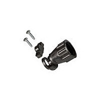
... Canada: 1-905-470-4425 Specifications subject Mexico: 52-55-1106-0800 to change. C. America: 57-1-254-4444 All part numbers Clamping Insert Cable Clamp Part No. Thread Individually Bulk Size Packaged Packaged* 1-206062-7** 1-206062-4 (400) 206966-9** 206966-7 (200) 1-206070-0** 206070-8 (200) 1-206138-0** 206138-8 (100) Clamping Insert Cable Clamp Part No. Thread Individually ...
Page 39
... Clamping Area Clamping (See Note 1) Insert Minimum Notes: 1. Clamping area is adjustable by inverting clamping inserts; maximum cable diameter is 1.125 [28.58]. 2. Components for cable clamp are packaged Clamping Insert unassembled. This includes the cable clamp, two screws (1.00 [25.4]) and the clamping inserts. ...
Page 40
... C Dia. Max. ±.015 B [±0.38] (2 Places) .156 [3.96] Ref. .280 [7.11] Part No .750 .125 207299-1 19.05 3.18 .875 .125 207299-2 22.22 3.18 1.110 .150 207299-3 28.19 3.81 1.510 .150 207299-4 38.35 3.81 South America: 55-11-2103-6000 Hong Kong: 852-2735-1628 Japan: 81-44-844-8013 UK: 44-208-420-8341 ...
Page 41
... Part Numbers 207489-1 (Cable Boot) 207490-1 (Cable Grip) Flexible Cable Boot and Internal Cable Grip .360 (for Shell Size 17) [9.14] Dia. Flexible cable boots, with internal cable grip installed, provide strain relief capabilities for jacketed cable in applications where aesthetic appearance is essential. They can be threaded onto plugs or receptacles ...
Page 42
... Values in brackets www.tycoelectronics.com are metric equivalents. Note: All part numbers are RoHS Compliant. (Continued) 1.000 [25.4] Series 1 and Series 4 Keying Plug (for Types III+ and Subminiature COAXICON Contacts) Part No. 200821-1 .200 ±.010 [5.08 ±0.25 ] .116 Max. [2.95] Dia. ...
Page 43
... Note: All part numbers are RoHS Compliant. capability to provide this product sealing to you in all the shell sizes. If you don’t see your particular size configuration, contact your local Tyco Electronics Sales Engineer or call Tyco Electronics for the latest information ...
Page 44
... Wire Entry Seal Plug Part Number 796075-1 (6 per carrier strip) Material—Polypropylene, natural Dimensions are shown for USA: 1-800-522-6752 reference purposes only. Canada: 1-905-470-4425 Specifications subject Mexico: 52-55-1106-0800 to change. C. America: 57-1-254-4444 Note: All part numbers are RoHS Compliant ...
Page 45
... AMP Circular Connectors for Commercial Signal and Power Applications One-Piece Sealed Circular Plastic Connectors, Series 5 CPC Connectors, Series 5 Square Flange Receptacle (Uses Flange Seal Part No. 81665-2 on page 51) Sealed – Reverse Sex 1.125 [28.58 1.435 [36.45] 1.125 [28.58 Listed part numbers are for connectors only ...
Page 46
... Canada: 1-905-470-4425 Specifications subject Mexico: 52-55-1106-0800 to change. C. America: 57-1-254-4444 Performance Characteristics Operating Temperature Range— -50°C to +125°C [-58˚F to +257˚F] UL Voltage Rating— Series 5 600 V (AC or DC) Series 6 250 V (AC or DC) .125 POWERBAND Power Contact – 45 amps, single contact rating at 30° ...
Page 47
... Note: Standard Size 8, High Current Upgrade Size 8, and .125 POWERBAND contacts are not intermateable. *A typical 626 Pneumatic Tool System requires: a power unit (Part No. 189721-2, hand actuated or 189722-2, foot actuated), an adapter holder (Part No. 356304-1, with ratchet), and “C” Head adapter Part No. 318161-1. ...
Page 48
... See page 38 for dimensional detail of cable clamp) or cable clamp kit 213904-3. (Similar to 206070-8. See page 38 for dimensional detail of cable clamp). Note: Minimum insulation diameter is .156 [3.96]; Maximum insulation diameter is .260 [6.60]. 48 Catalog 82021 Dimensions are in inches and Revised 7-07 millimeters unless otherwise specified ...
Page 49
... See page 38 for dimensional detail of cable clamp). Note: Minimum insulation diameter is .156 [3.96]; maximum insulation diameter is .260 [6.60] for power contacts. Minimum insulation diameter is .060 [1.50]; maximum insulation diameter is .130 [3.30] for signal contacts. Catalog 82021 Dimensions are in inches and ...
Page 50
... Rev. Four 4-40 threaded inserts per receptacle. 1 Notes: 1. For detailed performance data on peripheral seals, refer to Product Specification No. 108-10024. 2. Receptacles mate with Series 1 plugs found on page 10. Seal shown outside of connector for illustration purposes only. Receptacles with pre-installed, bonded peripheral seals are recommended for use in sealing/splash-proof applications, or where connectors will be subjected to vibration ...
Page 51
... Notes: 1. Kits include one Gang Seal and one Pressure Plate marked for cavity identification. Notes: 2. Arrangement No. 17-10 Insulation Dia. Range .176-.265 [4.52-6.73] for two holes, .075-125 [1.95-3.18] for eight holes. Part No. 81665-3 81665-4 1 ...