5536504-2 TE Connectivity, 5536504-2 Datasheet - Page 10
5536504-2
Manufacturer Part Number
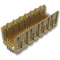
5536504-2
Description
Conn Backplane PIN 48 POS 2mm Press Fit ST Thru-Hole
Manufacturer
TE Connectivity
Type
Backplaner
Series
Z-PACKr
Specifications of 5536504-2
Pitch
2 mm
Number Of Rows
4
Number Of Contacts
48
Termination Method
Press Fit
Mounting
Through Hole
Contact Plating
Gold Over Nickel
Pitch (mm)
2mm
Gender
Pin
Body Orientation
Straight
Number Of Contact Rows
4
Mounting Style
Through Hole
Voltage Rating Max
30VAC
Contact Material
Phosphor Bronze
Housing Color
Natural
Housing Material
Liquid Cryst Polymer
Product Height (mm)
17mm
Product Depth (mm)
15.8mm
Product Length (mm)
23.88mm
Connector Type
Backplane
Row Pitch
2mm
Pitch Spacing
2mm
No. Of Contacts
48
Contact Termination
Press Fit
No. Of Rows
4
Contact
RoHS Compliant
Number Of Positions / Contacts
48
Mounting Angle
Vertical
Termination Style
Pin
Product Type
Connector
Pcb Mounting Orientation
Vertical
Post Type
Press-Fit
Module Type
Signal
Mating Post Length (mm [in])
6.50 [0.256]
Press-fit Post Style
Compliant Pin
Pin Header Width (mm [in])
16.00 [0.622]
Voltage Rating (vac)
30
Termination Post Length (mm [in])
4.25 [0.167]
Number Of Signal Positions
48
Sequencing
No
Post Plating
Tin
Centerline, Matrix (mm [in])
2.00 x 2.00 [.079 x .079]
Contact Type
Pin
Contact Base Material
Phosphor Bronze
Contact Plating, Mating Area, Material
Gold (30)
Connector Style
Plug
Rohs/elv Compliance
RoHS compliant, ELV compliant
Lead Free Solder Processes
Not relevant for lead free process
Rohs/elv Compliance History
Always was RoHS compliant
Applies To
Printed Circuit Board
Application
Fixed-Board
Lead Free Status / RoHS Status
Compliant
Lead Free Status / RoHS Status
Compliant


3.7. Soldering
Connectors with solder tines must be soldered to the pc board.
ALPHA, BIOACT, CARBITOL, KESTER, and LONCOTERGE are trademarks of their respective owners.
10 of 15
ALPHA 2110
BIOACT EC--7
CARBITOL
Isopropyl Alcohol
KESTER 5778
KESTER 5779
LONCOTERGE 520
LONCOTERGE 530
Terpene Solvent
DANGER
a pc board, all contact pins should be aligned and inserted into the pc board simultaneously to prevent
twisting or bending of the contacts. If using robotic equipment, a total equipment accuracy of +0.13 mm,
including the gripper and fixture tolerance and equipment repeatability, is required.
B. Seating Connectors
Seating force must be applied evenly on the connectors to prevent deformation or other damage to the
contacts and housings. The standoffs must be within 0.13 mm of the pc board (after insertion or
soldering). Refer to Paragraph 3.8.
When installing vertical pin header connectors with compliant pins, the insertion force must be
simultaneously applied to the shoulder of each contact on the inside floor surface of the connector. When
installing right--angle connectors with compliant contact pins, the insertion force must be evenly applied to
the back/top surface of the connector housing (see Figure 1) with a force of approximately 67 N per pin.
When installing vertical pin header connectors with solder tines, the insertion force must be evenly
distributed to the inside floor surface of the connector. When installing right--angle connectors with solder
tines, the insertion force must be evenly applied to the back/top surface of the connector housing (See
Figure 1) with a force of approximately 40 N per each 12 mm of length of the connector. Connectors will
remain securely on the pc board until passed through soldering providing that they are not jarred in any
manner. Tooling recommendations are covered in Section 5.
A. Flux Selection
The solder tines must be fluxed prior to soldering with a rosin base flux. Selection of the proper flux will
depend on the type of pc board and other components mounted on the pc board. The flux must be
compatible with the wave solder line, and all manufacturing and safety requirements.
B. Cleaning
After soldering, removal of fluxes, residues, and activators is necessary. Consult with the supplier of the
solder and flux for recommended cleaning solvents. A list of common cleaning solvents that will not affect
the connectors for the time and temperature specified is provided in Figure 8.
C. Drying
When drying cleaned assemblies and pc boards, do not exceed the temperature limitations of --55_ to
125_C [--99_ to 225_F]. Excessive temperatures may cause housing degradation.
To avoid personal injury, strict attention must be given to the recommendations of the solvent manufacturer regarding
toxicity and other safety requirements. Request the Material Safety Data Sheet (MSDS) from the supplier.
NAME
CLEANER
Aqueous
Aqueous
Aqueous
Aqueous
Aqueous
Solvent
Solvent
Solvent
Solvent
TYPE
Figure 8
(Minutes)
TIME
TIME
1
5
1
5
5
5
5
5
5
CELSIUS
TEMPERATURES (Max)
Room Ambience
132
100
100
100
100
100
100
100
FAHRENHEIT
270
212
212
212
212
212
212
212
114- 1075
Rev E
Related parts for 5536504-2
Image
Part Number
Description
Manufacturer
Datasheet
Request
R

Part Number:
Description:
Printers THERMAL PRINTER HS-SLEEVE MARKER
Manufacturer:
TE Connectivity


Part Number:
Description:
High Speed / Modular Connectors 30P HEADER ASSY
Manufacturer:
TE Connectivity
Datasheet:

Part Number:
Description:
High Speed / Modular Connectors REC 6X005P R/A LT B-PLANE HS3
Manufacturer:
TE Connectivity
Datasheet:

Part Number:
Description:
High Speed / Modular Connectors 2MM HM RCPT 50P R/A AU
Manufacturer:
TE Connectivity
Datasheet:

Part Number:
Description:
High Speed / Modular Connectors 2MM HM RCPT 50P R/A AU
Manufacturer:
TE Connectivity
Datasheet:


Part Number:
Description:
Manufacturer:
TE Connectivity
Datasheet:


Part Number:
Description:
Manufacturer:
TE Connectivity
Datasheet:

Part Number:
Description:
Manufacturer:
TE Connectivity
Datasheet:

Part Number:
Description:
Manufacturer:
TE Connectivity
Datasheet: