5223008-2 TE Connectivity, 5223008-2 Datasheet - Page 2
5223008-2
Manufacturer Part Number
5223008-2
Description
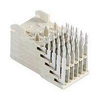
Conn Backplane RCP 60 POS 2mm Press Fit RA Thru-Hole
Manufacturer
TE Connectivity
Type
Backplaner
Series
Z-PACKr
Specifications of 5223008-2
Pitch
2 mm
Number Of Rows
5
Number Of Contacts
60
Termination Method
Press Fit
Mounting
Through Hole
Contact Plating
Gold Over Nickel
Row Pitch
2mm
Pitch Spacing
2mm
No. Of Contacts
60
Gender
Receptacle
Contact Termination
Press Fit
No. Of Rows
5
Contact Material
Phosphor Bronze
Rohs Compliant
Yes
Connector Type
Backplane
Number Of Positions / Contacts
60
Mounting Angle
Right
Mounting Style
PCB
Termination Style
Solder Pin
Housing Material
Liquid Crystal Polymer
Product Type
Connector
Pcb Mounting Orientation
Right Angle
Post Type
Press-Fit
Module Type
Signal
Voltage Rating (vac)
30
Termination Post Length (mm [in])
3.56 [0.140]
Number Of Signal Positions
60
Sequencing
No
Post Plating
Tin
Centerline, Matrix (mm [in])
2.00 x 2.00 [.079 x .079]
Contact Type
Socket
Contact Base Material
Phosphor Bronze
Contact Plating, Mating Area, Material
Gold (30)
Connector Style
Receptacle
Rohs/elv Compliance
RoHS compliant, ELV compliant
Lead Free Solder Processes
Not relevant for lead free process
Rohs/elv Compliance History
Always was RoHS compliant
Applies To
Printed Circuit Board
Application
Free-Board
Lead Free Status / Rohs Status
Details


3.3.
3.4.
3.5.
Rev C
Examination of product.
Termination resistance.
Insulation resistance.
Dielectric withstanding voltage.
Temperature rise vs current.
Ratings
!
!
!
!
Performance and Test Description
Product is designed to meet electrical, mechanical and environmental performance requirements
specified in Figure 1. Unless otherwise specified, all tests shall be performed at ambient environmental
conditions per Test Specification 109-1.
Test Requirements and Procedures Summary
Test Description
Voltage: 30 volts alternating current
Current:
•
•
Temperature: -55 to 125° C
Maximum Initial Contact Resistance: See Figure 1
Power: 3 amperes per contact
Signal: See Figure 5 for applicable current carrying capability
Row
A
B
C
D
Meets requirements of product
drawing.
See Figure 1
∆R 10 milliohms maximum.
5000 megohms minimum initial.
100 megohms minimum final.
1000 vac.
30° C maximum temperatur e rise at
specified current. Signal contacts
only.
Maximum Initial Contact Resistance (m )
Signal
Figure 2 (continued)
25
35
40
45
ELECTRICAL
Requirement
Figure 1
Power
10
10
10
10
Visual, dimensional and functional
per applicable quality inspection
plan.
TE 109-6-6.
Subject mated contacts assembled
in housing to 20 mv maximum
open circuit at 100 ma maximum.
See Figure 4.
TE Spec 109-28-4.
Test between adjacent contacts of
mated samples.
TE Spec 109-29-1.
Test between adjacent contacts of
mated samples. Test a minimum of
5 contacts per sample.
TE Spec 109-45-1.
Measure temperature rise vs
current.
See Figure 5.
Procedure
108-1441
2 of 8
Related parts for 5223008-2
Image
Part Number
Description
Manufacturer
Datasheet
Request
R

Part Number:
Description:
Printers THERMAL PRINTER HS-SLEEVE MARKER
Manufacturer:
TE Connectivity


Part Number:
Description:
High Speed / Modular Connectors 30P HEADER ASSY
Manufacturer:
TE Connectivity
Datasheet:

Part Number:
Description:
High Speed / Modular Connectors REC 6X005P R/A LT B-PLANE HS3
Manufacturer:
TE Connectivity
Datasheet:


Part Number:
Description:
Manufacturer:
TE Connectivity
Datasheet:


Part Number:
Description:
Manufacturer:
TE Connectivity
Datasheet:

Part Number:
Description:
Manufacturer:
TE Connectivity
Datasheet:

Part Number:
Description:
Manufacturer:
TE Connectivity
Datasheet:


Part Number:
Description:
Manufacturer:
TE Connectivity
Datasheet: