BT137S-600E,118 NXP Semiconductors, BT137S-600E,118 Datasheet - Page 2
BT137S-600E,118
Manufacturer Part Number
BT137S-600E,118
Description
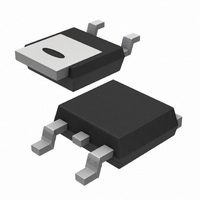
TRIAC 600V 8A TO220AB
Manufacturer
NXP Semiconductors
Type
TRIACr
Specifications of BT137S-600E,118
Package / Case
TO-252-3, DPak (2 Leads + Tab), SC-63
Triac Type
Logic - Sensitive Gate
Mounting Type
Surface Mount
Configuration
Single
Current - Hold (ih) (max)
20mA
Voltage - Off State
600V
Current - Gate Trigger (igt) (max)
10mA
Current - Non Rep. Surge 50, 60hz (itsm)
65A, 71A
Current - On State (it (rms)) (max)
8A
Voltage - Gate Trigger (vgt) (max)
1.5V
Current - On State (it (rms) (max)
8A
Rated Repetitive Off-state Voltage Vdrm
600 V
Breakover Current Ibo Max
71 A
Off-state Leakage Current @ Vdrm Idrm
0.5 mA
Gate Trigger Voltage (vgt)
1.5 V
Gate Trigger Current (igt)
25 mA
Holding Current (ih Max)
20 mA
Forward Voltage Drop
1.65 V @ 10 A
Mounting Style
SMD/SMT
Repetitive Peak Forward Blocking Voltage
600 V
Repetitive Peak Off-state Volt
600V
Off-state Voltage
600V
Hold Current
20mA
Gate Trigger Current (max)
25mA
Gate Trigger Voltage (max)
1.5V
Package Type
DPAK
Peak Repeat Off Current
500uA
Peak Surge On-state Current (max)
71A
On State Voltage(max)
1.65@10AV
Mounting
Surface Mount
Pin Count
2 +Tab
Operating Temp Range
-40C to 125C
Operating Temperature Classification
Automotive
Lead Free Status / RoHS Status
Lead free / RoHS Compliant
Lead Free Status / RoHS Status
Lead free / RoHS Compliant, Lead free / RoHS Compliant
Other names
568-3661-2
934049430118
BT137S-600E /T3
934049430118
BT137S-600E /T3
Available stocks
Company
Part Number
Manufacturer
Quantity
Price
Company:

Part Number:
BT137S-600E,118
Manufacturer:
NXP Semiconductors
Quantity:
1 000


Philips Semiconductors
THERMAL RESISTANCES
STATIC CHARACTERISTICS
T
DYNAMIC CHARACTERISTICS
T
June 2001
Triacs
sensitive gate
SYMBOL PARAMETER
R
R
j
SYMBOL PARAMETER
I
I
I
V
V
I
j
SYMBOL PARAMETER
dV
t
GT
L
H
D
gt
= 25 ˚C unless otherwise stated
= 25 ˚C unless otherwise stated
T
GT
th j-mb
th j-a
D
/dt
Thermal resistance
junction to mounting base half cycle
Thermal resistance
junction to ambient
Gate trigger current
Latching current
Holding current
On-state voltage
Gate trigger voltage
Off-state leakage current
Critical rate of rise of
off-state voltage
Gate controlled turn-on
time
CONDITIONS
full cycle
pcb (FR4) mounted; footprint as in Fig.14
CONDITIONS
V
V
V
I
V
V
V
CONDITIONS
V
exponential waveform; gate open circuit
I
dI
T
TM
D
D
D
D
D
D
DM
G
= 10 A
/dt = 5 A/ s
= 12 V; I
= 12 V; I
= 12 V; I
= 12 V; I
= 400 V; I
= V
= 12 A; V
= 67% V
DRM(max)
T
GT
GT
T
D
T
DRM(max)
= 0.1 A
= 0.1 A
; T
= 0.1 A
= 0.1 A
= V
= 0.1 A; T
j
2
= 125 ˚C
DRM(max)
; T
j
= 125 ˚C;
j
; I
= 125 ˚C
G
= 0.1 A;
T2+ G+
T2+ G-
T2- G-
T2- G+
T2+ G+
T2+ G-
T2- G-
T2- G+
MIN.
MIN.
MIN.
0.25
-
-
-
-
-
-
-
-
-
-
-
-
-
-
-
-
-
BT137S series E
TYP.
TYP.
TYP.
2.5
4.0
5.0
3.0
3.0
4.0
2.5
1.3
0.7
0.4
0.1
75
11
14
50
2
-
-
Product specification
MAX.
MAX.
MAX.
1.65
2.0
2.4
1.5
0.5
10
10
10
25
25
35
25
35
20
-
-
-
-
Rev 1.400
UNIT
UNIT
UNIT
V/ s
K/W
K/W
K/W
mA
mA
mA
mA
mA
mA
mA
mA
mA
mA
V
V
V
s
Related parts for BT137S-600E,118
Image
Part Number
Description
Manufacturer
Datasheet
Request
R

Part Number:
Description:
TRIAC 600V 8A SOT428
Manufacturer:
NXP Semiconductors
Datasheet:
Part Number:
Description:
TRIAC 600V 8A DPAK
Manufacturer:
NXP Semiconductors
Datasheet:

Part Number:
Description:
Planar passivated four quadrant triac in a SOT428 (DPAK) surface-mountable plastic package intended for use in bidirectional switching and phase control applications
Manufacturer:
NXP Semiconductors
Datasheet:
Part Number:
Description:
Planar passivated very sensitive gate four quadrant triac in a SOT428 (DPAK) surface-mountable plastic package intended for use in general purpose bidirectional switching and phase control applications, where high sensitivity is required in all four
Manufacturer:
NXP Semiconductors
Datasheet:
Part Number:
Description:
Planar passivated sensitive gate four quadrant triac in a SOT428 (DPAK) surface-mountable plastic package intended for use in general purpose bidirectional switching and phase control applications
Manufacturer:
NXP Semiconductors
Datasheet:
Part Number:
Description:
Planar passivated four quadrant triac in a SOT428 (DPAK) surface-mountable plastic package intended for use in general purpose bidirectional switching and phase control applications
Manufacturer:
NXP Semiconductors
Datasheet:
Part Number:
Description:
Planar passivated four quadrant triac in a SOT428 (DPAK) surface-mountable plastic package intended for use in general purpose bidirectional switching and phase control applications
Manufacturer:
NXP Semiconductors
Datasheet:
Part Number:
Description:
Planar passivated sensitive gate four quadrant triac in a SOT428 (DPAK) surface-mountable plastic package intended for use in general purpose bidirectional switching and phase control applications
Manufacturer:
NXP Semiconductors
Datasheet:
Part Number:
Description:
Planar passivated four quadrant triac in a SOT428 (DPAK) surface-mountable plastic package intended for use in general purpose bidirectional switching and phase control applications
Manufacturer:
NXP Semiconductors
Datasheet:
Part Number:
Description:
Planar passivated four quadrant triac in a SOT428 (DPAK) surface-mountable plastic package intended for use in general purpose bidirectional switching and phase control applications
Manufacturer:
NXP Semiconductors
Datasheet:

Part Number:
Description:
Manufacturer:
Philips Semiconductors
Datasheet:
Part Number:
Description:
TRIAC 600V 8A SOT428
Manufacturer:
NXP Semiconductors
Datasheet:
Part Number:
Description:
TRIAC 600V 8A SOT428
Manufacturer:
NXP Semiconductors
Datasheet:
Part Number:
Description:
TRIAC 800V 8A SOT428
Manufacturer:
NXP Semiconductors
Datasheet:
Part Number:
Description:
TRIAC 800V 8A SOT428
Manufacturer:
NXP Semiconductors
Datasheet: