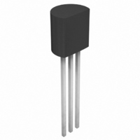
ACS102-5TA-TR STMicroelectronics, ACS102-5TA-TR Datasheet - Page 5

ACS102-5TA-TR
Manufacturer Part Number
ACS102-5TA-TR
Description
IC AC LINE SWITCH TO-92
Manufacturer
STMicroelectronics
Series
ASD™r
Datasheet
1.ACS102-5TA-TR.pdf
(8 pages)
Specifications of ACS102-5TA-TR
Triac Type
Logic - Sensitive Gate
Mounting Type
Through Hole
Configuration
Single
Current - Hold (ih) (max)
20mA
Voltage - Off State
500V
Current - Gate Trigger (igt) (max)
5mA
Current - Non Rep. Surge 50, 60hz (itsm)
7.3A, 8A
Current - On State (it (rms)) (max)
200mA
Voltage - Gate Trigger (vgt) (max)
900mV
Package / Case
TO-92-3 (Standard Body), TO-226
Current - On State (it (rms) (max)
200mA
Lead Free Status / RoHS Status
Lead free / RoHS Compliant
Other names
497-3113-2
Fig. 5: Maximum power dissipation versus RMS
on-state current.
Fig. 8: Relative variation of gate trigger current
versus junction temperature.
3.0
2.5
2.0
1.5
1.0
0.5
0.0
0.20
0.18
0.16
0.14
0.12
0.10
0.08
0.06
0.04
0.02
0.00
Fig. 7-1: Relative variation of thermal impedance
junction to ambient versus pulse duration
(ACS102-5TA) (TO-92).
1.00
0.10
0.01
-40
1E-3
0.00 0.02 0.04 0.06 0.08 0.10 0.12 0.14 0.16 0.18 0.20
IGT [Tj] / IGT [Tj=25°C]
P(W)
Zth(j-a) / Rth(j-a)
-20
1E-2
0
20
1E-1
IT(RMS)(A)
40
Tj(°C)
tp(s)
1E+0
60
1E+1
80
100
1E+2 5E+2
120
140
Fig. 6:
temperature.
Fig. 9: Relative variation of holding and latching
current versus junction temperature.
0.25
0.20
0.15
0.10
0.05
0.00
Fig. 7-2: Relative variation of thermal impedance
junction to ambient versus pulse duration (printed
circuit board FR4, e(Cu) = 35 m, S(Cu) = 40mm
under “com” pins) (ACS102-5T1) (SO-8).
1.00
0.10
0.01
2.0
1.8
1.6
1.4
1.2
1.0
0.8
0.6
0.4
0.2
0.0
-40
1E-3
IH,IL [Tj] / IH,IL [Tj=25°C]
0
Zth(j-a) / Rth(j-a)
IT(RMS)(A)
-20
20
RMS on-state current versus ambient
1E-2
0
40
20
1E-1
60
Tamb(°C)
40
Tj(°C)
tp(s)
1E+0
60
80
80
1E+1
100
ACS102-5Tx
100
1E+2 5E+2
120
120
140
5/8
140
2


