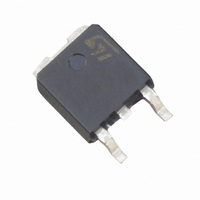
ACST4-7SB-TR STMicroelectronics, ACST4-7SB-TR Datasheet - Page 6

ACST4-7SB-TR
Manufacturer Part Number
ACST4-7SB-TR
Description
IC SWITCH LINE AC PWR ASD DPAK
Manufacturer
STMicroelectronics
Datasheet
1.ACST4-7CH.pdf
(13 pages)
Specifications of ACST4-7SB-TR
Triac Type
Standard
Mounting Type
Surface Mount
Configuration
Single
Current - Hold (ih) (max)
35mA
Voltage - Off State
700V
Current - Gate Trigger (igt) (max)
25mA
Current - Non Rep. Surge 50, 60hz (itsm)
30A, 33A
Current - On State (it (rms)) (max)
4A
Voltage - Gate Trigger (vgt) (max)
1.1V
Package / Case
TO-252-3, DPak (2 Leads + Tab), SC-63
Current - On State (it (rms) (max)
4A
Lead Free Status / RoHS Status
Lead free / RoHS Compliant
Other names
497-2555-2
497-4150-2
497-4150-2
497-4150-2
497-4150-2
Application information
2
2.1
6/13
Application information
Typical application description
The ACST4 device has been designed to control medium power load, such as AC motors in
home appliances. Thanks to its thermal and turn off commutation performances, the ACST4
switch is able to drive an inductive load up to 4 A with no turn off additional snubber. It also
provides high thermal performances in static and transient modes such as the compressor
inrush current or high torque operating conditions of an AC motor. Thanks to its low gate
triggering current level, the ACST4 can be driven directly by an MCU through a simple gate
resistor as shown
Figure 16. Compressor control – typical diagrams
AC Mains
Compressor with integrated e-starter
Power supply
Compressor
Figure 16
PTC
ACST
ACST
Driver
Gate
and
thermostat
Electronic
Doc ID 8766 Rev 5
1
Figure
Rg
logical circuitry
Electronic
starter
17.
Power supply
AC Mains
Compressor with external electronic drive
switch
Run
Driver
Gate
ACST
Compressor
PTC
Rg
ACST
ASCT4
Rg
switch
Start


