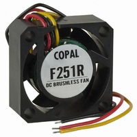
F251RF-12LLB Copal Electronics Inc, F251RF-12LLB Datasheet - Page 2

F251RF-12LLB
Manufacturer Part Number
F251RF-12LLB
Description
FAN 12VDC 25X10MM .36W 1.41CFM
Manufacturer
Copal Electronics Inc
Series
F251RFr
Datasheet
1.F251RF-12LLB.pdf
(2 pages)
Specifications of F251RF-12LLB
Fan Type
Tubeaxial
Size / Dimension
Square - 25mm L x 25mm H x 10mm W
Voltage - Rated
12VDC
Power (watts)
0.36W
Features
Speed Sensor (Tach)
Rpm
6500 RPM
Noise
11 dB(A)
Static Pressure
0.080 in H2O (19.9 Pa)
Air Flow
1.4 CFM (0.040m³/min)
Termination
3 Wire Leads
Bearing Type
1 Ball/1 Sleeve
Weight
0.015 lb (6.8g)
Current Rating
30mA
Voltage Range
10.2 ~ 13.8VDC
Operating Temperature
14 ~ 140°F (-10 ~ 60°C)
Termination Style
11 dB(A)
Lead Free Status / RoHS Status
Lead free / RoHS Compliant
Other names
563-1120
■ STANDARD SPECIFICATIONS
❈ : Figures in the table are typical values under rated operating condition.
■ FG SIGNAL CHARACTERISTICS
❈ : 2 conditions are possible according to the stop position of the impeller.
■ OUTLINE DIMENSIONS
■ Specifications are subject to change without notice. Specifications in this catalog are for reference. The formal specification sheets will be submitted upon request.
Rated voltage
Voltage range
Rated current
Rotating speed
Air flow
Static pressure
Noise
Net weight
Output circuit
Maximum output voltage
Maximum sink current
Output saturation voltage (at Low)
Output (rotate)
Output (lock)
Time a High Signal (lock)
1 “High” (Fixed) : Constantly “High”
2 “High/Low” intermittent motion : “High” and “Low” switch at regular time intervals.
Item
10±0.5
Item
Air flow
F251RF-05LLB
4.2 ~ 5.7 V
DC5 V
0.05 A
It is guaranteed that “high” continues over 0.5 seconds.
High or High/Low intermittent motion
F251RF-12LLB
Vsat : Maximum 0.4 V
0.04 m
Approx. 7 g
6500 min
11 dB (A)
4 pulses / rotation
20±0.5
DC12 V
0.5 s minimum
20 Pa
Specification
Open collector
□
Lead wire UL1685 AWG28
Black : 0 V
Red : B
Yellow : FG
25
3
/min
5 mA
15 V
10.2 ~ 13.8 V
❈
-1
0.03 A
Rated voltage
4 – C2
4 – 2.8
F251RF-12LLC
φ
DC12 V
■ AIR FLOW PERFORMANCE CURVES
● FAN condition and FG sighal
● Output circuitry
Power +
GND
FG signal
FG signal
FAN condition
FAN condition
Red
Black
High
Low
High
Low
Lock
Rotation
Dimension of mounting hole for recommendation
10
COPAL ELECTRONICS
25
20
15
5
0
Collector
20±0.5
One rotation
BRUSHLESS DC FANS
0.5 s (minimum)
0.02
Rotation
Air flow (m
Yellow
Do not exceed maximum
sink current
I
Pull up
0.04
3
/min)
Stop
4 – 2.8
F251RF
Pull up resistance
Approx. 10 kΩ
Connect to any voltage
Do not exceed maximum
output voltage
0.06
φ
(Unit: mm)
Lock
Stop
2005
Oct,


