W2G115-AG71-12 EBM-Papst Industries Inc, W2G115-AG71-12 Datasheet - Page 5
W2G115-AG71-12
Manufacturer Part Number
W2G115-AG71-12
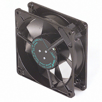
Description
FAN 127 X 38MM 24VDC
Manufacturer
EBM-Papst Industries Inc
Series
W2G115r
Type
Tubeaxialr
Datasheets
1.W2G115-AD15-13.pdf
(1 pages)
2.W2G115-AG71-12.pdf
(8 pages)
3.W2G115-AG71-12.pdf
(1 pages)
Specifications of W2G115-AG71-12
Bearing Type
Ball
Fan Type
Tubeaxial
Size / Dimension
Square - 127mm L x 127mm H x 38mm W
Voltage - Rated
24VDC
Power (watts)
12.0W
Features
Locked Rotor Sensor
Rpm
4050 RPM
Noise
52 dB(A)
Air Flow
160.0 CFM (4.53m³/min)
Termination
2 Terminals
Weight
1.2 lbs (544.3g)
Voltage Range
16 ~ 28VDC
Termination Style
52 dB(A)
External Height
127mm
External Width
127mm
External Depth
38mm
Current Type
DC
Supply Voltage
24VDC
Flow Rate
160CFM
Noise Rating
52dBA
Power Connection Type
Terminal
Brand/series
W2G117
Dimensions
127 x 127 x 38 mm
Noise Level
52 dBA
Power Rating
12 W
Size
5 x 1.5 (127 x 38) In. (mm)
Voltage, Rating
24 V
Flow Rate - Imperial
160CFM
Rohs Compliant
Yes
Lead Free Status / RoHS Status
Lead free / RoHS Compliant
Static Pressure
-
Lead Free Status / Rohs Status
Lead free / RoHS Compliant
Other names
381-1068
W2G115-AG71-13
W2G115AG7112
W2G115AG7113
W2G115-AG71-13
W2G115AG7112
W2G115AG7113


3.2 Nominal data
ml = max. load · me = max. efficiency · rfa = running at free air
cs = customer specs · cu = customer unit
Subject to alterations
3.3 Technical description
3.4 Mounting data
For depth of screw, see chapter 3.1 Graphic rendition of products
You can obtain additional mounting data from the product drawing if
necessary.
3.5 Transport and storage conditions
Item no.: 50987-5-9970 · Revision status: KM72138 · Print-out on 02/12/2010 · Created by A. Kehm (VM---) · Page 5 of 8
ebm-papst Mulfingen GmbH & Co. KG · Bachmühle 2 · D-74673 Mulfingen · Phone: +49(0)7938/81-0 · Fax: +49(0)7938/81-110 · info1@de.ebmpapst.com · www.ebmpapst.com
Motor
Nominal voltage [VDC]
Nominal voltage
range [VDC]
Type of data definition
State
Speed [min
Power input [W]
Min. ambient
temperature [°C]
Max. ambient
temperature [°C]
Size
Operation mode
Direction of rotation
Mounting position
Direction of air flow
Insulation class
Condensate discharge
holes
Bearing motor
Mass
Material of blades
Material of wall ring
Motor protection
Surface of rotor
Number of blades
Type of protection
Strength class for
mounting screws
Max. permissible
ambient motor temp.
(transp./ storage)
Min. permissible
ambient motor temp.
(transp./storage)
W2G115-AG71-12
Secure the mounting screws against accidentally coming loose (e.g.
by using self-locking screws).
Use the device in accordance with its protection type.
-1
]
115 mm
S1
Counter-clockwise, seen on rotor
Any
"V"
"B"
Rotor-side
Ball bearing
0.55 kg
Sheet steel, coated in black
Die-cast aluminium, coated in black
Reverse polarity and locked-rotor
protection
Coated in black
7
IP 22
8.8
+ 80 °C
- 40 °C
M2G045-BA
24
16 .. 28
rfa
prelim.
4050
12
-25
+72
Operating instructions
4. CONNECTION AND START-UP
4.1 Connecting the mechanical system
4.2 Connecting the electrical system
4.2.1 Prerequisites
4.3 Connection via plug
4.3.1 Preparing connection lines for the connection
Check the device for transport damage. Damaged devices must no
longer be installed.
Install the undamaged device according to your application.
Check whether the data on the type plate agree with the connection
data.
Before connecting the device, ensure that the supply voltage matches
the operating voltage of the device.
Only use cables designed for current according to the type plate.
Connect the connection lines to the mating connectors.
CAUTION
Cutting and crushing hazard when removing the fan
from the packaging
CAUTION
Electrical voltage
The fan is a built-in component and features no electrically
isolating switch.
NOTE
Water penetration into leads or wires
Water enters at the cable end on the customers side and can
damage the device.
Operate the device with a safely isolated power pack.
The lines, including customer-side interface, fall within the
standard of the internal connection.
Observe product conformity to standards and the type of
protection in your end device after you have installed the ebm-
papst device.
Carefully lift the fan out of its packaging, only touching the
housing. Make sure to avoid any shock.
Wear safety shoes and cut-resistant safety gloves.
Only connect the fan to circuits that can be switched off with
an all-pole separating switch.
When working on the fan, you must switch off the
installation/machine in which the fan is installed and secure it
from being switched on again.
Make sure that the cable end is connected in a dry
environment.
Related parts for W2G115-AG71-12
Image
Part Number
Description
Manufacturer
Datasheet
Request
R

Part Number:
Description:
FAN EXHAUST 127 X 38MM 12VDC
Manufacturer:
EBM-Papst Industries Inc
Datasheet:

Part Number:
Description:
FAN TUBEAXIAL 127X38MM 12VDC
Manufacturer:
EBM-Papst Industries Inc
Datasheet:

Part Number:
Description:
FAN EXHAUST 127 X 38MM 24VDC
Manufacturer:
EBM-Papst Industries Inc
Datasheet:

Part Number:
Description:
FAN EXHAUST 127 X 38MM 12VDC
Manufacturer:
EBM-Papst Industries Inc
Datasheet:
Part Number:
Description:
FAN TUBEAXIAL 127X38MM 12VDC
Manufacturer:
EBM-Papst Industries Inc
Datasheet:
Part Number:
Description:
FAN TUBEAXIAL 127X38MM 24VDC
Manufacturer:
EBM-Papst Industries Inc
Datasheet:
Part Number:
Description:
FAN TUBEAXIAL 127X38MM 48VDC
Manufacturer:
EBM-Papst Industries Inc
Datasheet:
Part Number:
Description:
AC Axial Fan
Manufacturer:
EBM-Papst Industries Inc
Datasheet:
Part Number:
Description:
AC Axial Fan
Manufacturer:
EBM-Papst Industries Inc
Datasheet:

Part Number:
Description:
FAN, 24(16-28V), 4050RPM, 12W
Manufacturer:
EBM-Papst Industries Inc
Datasheet:

Part Number:
Description:
FAN EXHAUST 119 X 25MM 230VAC
Manufacturer:
EBM-Papst Industries Inc
Datasheet:

Part Number:
Description:
FAN TUBEAXIAL 92X38MM 230VAC
Manufacturer:
EBM-Papst Industries Inc
Datasheet:

Part Number:
Description:
FAN 92 X 32MM 12VDC
Manufacturer:
EBM-Papst Industries Inc
Datasheet:

Part Number:
Description:
FAN TUBEAXIAL 40X20MM 5VDC
Manufacturer:
EBM-Papst Industries Inc
Datasheet:

Part Number:
Description:
AC Tubeaxial Fan
Manufacturer:
EBM-Papst Industries Inc
Datasheet: