193839-2 TE Connectivity, 193839-2 Datasheet - Page 5
193839-2
Manufacturer Part Number
193839-2
Description
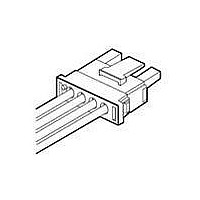
Conn Wire to Board SKT 3 POS 6.35mm Solder RA Thru-Hole
Manufacturer
TE Connectivity
Type
Wire to Boardr
Datasheet
1.206036-8.pdf
(64 pages)
Specifications of 193839-2
Pitch
6.35 mm
Number Of Rows
1
Number Of Contacts
3
Gender
SKT
Contact Plating
Silver Over Nickel
Termination Method
Solder
Product Type
Headers
Contact Gender
Socket (Female)
Voltage Rating
600 V
Current Rating
31 A
Number Of Positions / Contacts
3
Mounting Style
Panel
Contact Material
Copper Alloy
Housing Material
Polyamide
Product Line
Universal MATE-N-LOK II
Connector Type
Header
Color
Natural
Pcb Mount Alignment
Without
Mount Angle
Right Angle
Mating Retention Type
Positive Lock
High Current
Yes
Current Rating (a)
31
Voltage (vac)
600
Termination Post Length (mm [in])
4.06 [0.160]
Solder Tail Contact Plating
Silver
Centerline (mm [in])
6.35 [0.250]
Number Of Positions
3
Mating Retention
With
Louvertac Band Material
Beryllium Copper
Contact Type
Socket
Contact Layout
In-Line
Contact Termination Type
Through Hole
Contact Plating, Mating Area, Material
Silver
Contact Base Material
Copper Alloy
Sealable
No
Connector Style
Receptacle
Ul Flammability Rating
UL 94V-0
Rohs/elv Compliance
RoHS compliant, ELV compliant
Lead Free Solder Processes
Wave solder capable to 240°C, Wave solder capable to 260°C, Wave solder capable to 265°C
Rohs/elv Compliance History
Always was RoHS compliant
Applies To
Printed Circuit Board
Pcb Thickness, Recommended (mm [in])
1.57 [0.062]
Lead Free Status / Rohs Status
Details
Available stocks
Company
Part Number
Manufacturer
Quantity
Price
Company:

Part Number:
193839-2
Manufacturer:
TE Connectivity AMP Connectors
Quantity:
231


Catalog 82045
Revised 06-08
www.tycoelectronics.com
Dimensions are in millimeters
and inches unless otherwise
specified. Values in brackets are
equivalent U.S. Customary Units.
AMP Metrimate
Pin and Socket Connectors
Performance Characteristics
•
Practical Values
The current-rating method
gives designers practical val-
ues applicable to their appli-
cations. While the specified
current levels for a contact
may be lower than for other
testing methods, they are
more realistic and simplify
the system design process.
"Spec-manship" is replaced
by a realistic assessment of
the current-carrying capacity
of a contact under varying
conditions of temperature,
connector loading, and wire
size.
contact. The curve is usu-
ally flat up to 75°C ambient
and then drops off. Up to
75°C, the 30°C T-rise limits
the amount of current, and
above 75°C the current
must be reduced to keep
the combination of ambi-
ent temperature and T-rise
from exceeding the maxi-
mum operating tempera-
ture of 105°C.
Next are rating factors, a
table of multipliers to
account for connector
loading and for smaller
wire sizes. The designer
first determines the base
current for the ambient
conditions of the applica-
tion, then multiplies this
base current by the rating
factors to find the current
level for the application's
loading factor and wire
size.
Dimensions are shown for
reference purposes only.
Specifications subject
to change.
Graph shows the relationship between base current, ambient tem-
perature, and contact T-rise.
Rating factors allow the base current to be adjusted for various con-
nector loading and wire sizes.
An Example:
To demonstrate the method of specifying current, consider the
following application conditions, an ambient temperature of
65°C, a 50% loading of contacts in the housing, and 20 AWG
[0.6 mm2] wire.
•
•
•
•
•
0
From Figure 1, the base current rating is 14 ampere with 18
AWG [0.8 mm2] wire.
Figure 2, the rating factor for 50% loading and 20 AWG [0.6
mm2] wire is 0.68.
The specific rating for this application is the product of the
base rating and the rating factor:
Each of the contacts can carry 9.5 ampere.
However, if the ambient temperature is 80
T-rise becomes 25°C. The base current must be lowered to
12.8 ampere so that the 105
ture is not exceeded. The current rating then becomes:
Single
100%
12.8 x 0.68 = 8.7 ampere.
30%
50%
70%
14 x 0.68 = 9.5 ampere
10
USA: 1-800-522-6752
Canada: 1-905-470-4425
Mexico: 01-800-733-8926
C. America: 52-55-5-729-0425
(Continued)
20
NOTE: All part numbers
are RoHS Compliant
.97
.83
.65
.55
18
1
30
Ambient Temperature (°C)
40
.83
.80
.68
.53
.45
20
50
°
Figure 2
Figure 1
C maximum operating tempera-
AWG
.69
.66
.57
.45
.38
22
60
South America: 55-11-3611-1514
Hong Kong: 852-2735-1628
Japan: 81-44-844-8013
UK: 44-141-810-8967
70
.59
.57
.48
.38
.32
24
°C the allowable
80
Single Contact
.50
.49
.42
.33
.28
26
90
[0.8 mm
18 AWG
100
2
]
15
10
5
0
5
Related parts for 193839-2
Image
Part Number
Description
Manufacturer
Datasheet
Request
R

Part Number:
Description:
Conn Wire to Board HDR 2 POS 6.35mm Solder RA Thru-Hole
Manufacturer:
TE Connectivity
Datasheet:
Part Number:
Description:
Conn Wire to Board HDR 4 POS 6.35mm Solder RA Thru-Hole
Manufacturer:
TE Connectivity
Datasheet:
Part Number:
Description:
SKT HEADER, RIGHT ANGLE
Manufacturer:
TE Connectivity
Datasheet:

Part Number:
Description:
Printers THERMAL PRINTER HS-SLEEVE MARKER
Manufacturer:
TE Connectivity


Part Number:
Description:
High Speed / Modular Connectors 30P HEADER ASSY
Manufacturer:
TE Connectivity
Datasheet:

Part Number:
Description:
High Speed / Modular Connectors REC 6X005P R/A LT B-PLANE HS3
Manufacturer:
TE Connectivity
Datasheet:

Part Number:
Description:
High Speed / Modular Connectors 2MM HM RCPT 50P R/A AU
Manufacturer:
TE Connectivity
Datasheet:

Part Number:
Description:
High Speed / Modular Connectors 2MM HM RCPT 50P R/A AU
Manufacturer:
TE Connectivity
Datasheet:


Part Number:
Description:
Manufacturer:
TE Connectivity
Datasheet:


Part Number:
Description:
Manufacturer:
TE Connectivity
Datasheet:

Part Number:
Description:
Manufacturer:
TE Connectivity
Datasheet:

Part Number:
Description:
Manufacturer:
TE Connectivity
Datasheet: