5-103958-1 TE Connectivity, 5-103958-1 Datasheet - Page 19
5-103958-1
Manufacturer Part Number
5-103958-1
Description
Conn IDC Connector RCP 2 POS 2.54mm IDT ST Cable Mount Strip
Manufacturer
TE Connectivity
Type
IDC Connectorr
Series
AMPMODU MTEr
Datasheet
1.103682-1.pdf
(32 pages)
Specifications of 5-103958-1
Pitch
2.54 mm
Number Of Rows
1
Number Of Contacts
2
Gender
RCP
Contact Plating
Gold Over Nickel
Termination Method
IDT
Connector Type
Wire To Board
Contact Termination
IDC / IDT
No. Of Contacts
2
No. Of Rows
1
Pitch Spacing
2.54mm
Rohs Compliant
Yes
Product Type
Connector
Termination Method To Wire/cable
Crimp, Insulation Displacement Crimp (IDC)
Mating Connector Lock
With
Wire Insulation Diameter (mm [in])
1.37 [0.054]
Connector Series
MTE
Keyed
No
Applied Pressure
Standard
Contact - Rated Current (a)
3
Termination Resistance (m?)
15
Insulation Resistance (m?)
5,000
Dielectric Withstanding Voltage (v)
600
Solder Tail Contact Plating
Tin
Centerline (mm [in])
2.54 [0.100]
Row-to-row Spacing (mm [in])
2.54 [0.100]
Number Of Positions
2
Wire Range (mm [awg])
0.12-0.40² [26-22]
Contact Type
Socket
Contact Plating, Mating Area, Material
Gold (30)
Contact Base Material
Phosphor Bronze
Connector Style
Receptacle
Mating Alignment
With
Mating Alignment Type
Latched
Housing Color
Black
Ul Flammability Rating
UL 94V-0
Housing Material
Thermoplastic - GF
Rohs/elv Compliance
RoHS compliant, ELV compliant
Lead Free Solder Processes
Not relevant for lead free process
Rohs/elv Compliance History
Always was RoHS compliant
Approved Standards
UL E28476, CSA LR7189
Operating Temperature (°c)
-65 – +105
Applies To
Wire/Cable
Packaging Method
Strip
Quantity Per Strip
10


Double-Row
Material
Black thermoplastic, 94V-0 rated
Technical Documents
pages 277, 278
Product Specification
108-25034
Application Specification
114-25026
Catalog 1307819
Revised 8-08
www.tycoelectronics.com
—
are metric equivalents.
Dimensions are in inches and
millimeters unless otherwise
specified. Values in brackets
AMPMODU Interconnection System
Coupling Shrouds for MTE Receptacle Assemblies with Guide Ribs
1
1
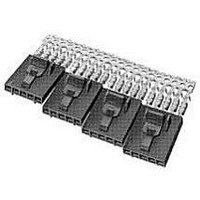
Typical Application of Double-Row Coupling Shroud and Mating AMPMODU Products
Note: All part numbers are RoHS compliant.
Mating AMPMODU Double-Row Shrouded Headers must have .318 [8.08] mating post length and .150 [3.81] dimension from centerline
of last post to inside of end shroud wall.
Assemblies with Guide
Ribs (Refer to pages
232, 233 & 235)
Position No. 1
Identification
Receptacle
Dimensions are shown for
reference purposes only.
Specifications subject
to change.
Coupling Shroud
Double-Row
Headers Double-Row, Straight
No. of
Pos.
AMPMODU Shrouded
or Right–Angle Post
10
12
14
16
18
20
22
24
26
28
30
32
34
40
50
8
A
1.085 [27.56]
1.185 [30.10]
1.285 [32.64]
1.385 [35.18]
1.485 [37.72]
1.585 [40.26]
1.685 [42.80]
1.785 [45.34]
1.885 [47.88]
2.185 [55.50]
2.685 [68.20]
.585 [14.86]
.685 [17.40]
.785 [19.94]
.885 [22.48]
.985 [25.02]
Dimension
USA: 1-800-522-6752
Canada: 1-905-470-4425
Mexico: 01-800-733-8926
C. America: 52-55-1106-0803
1
A
Coupling Shroud
Double-Row
1-104500-0
1-104500-1
103681-1
103681-2
103681-3
103681-4
103681-5
104500-1
104500-2
104500-3
104500-4
104500-5
104500-6
104500-7
104500-8
104500-9
South America: 55-11-2103-6000
Hong Kong: 852-2735-1628
Japan: 81-44-844-8013
UK: 44-8706-080-208
[18.67]
.735
(Continued)
241
5
Related parts for 5-103958-1
Image
Part Number
Description
Manufacturer
Datasheet
Request
R

Part Number:
Description:
Conn Unshrouded Header HDR 10 POS 2.54mm Solder ST SMD
Manufacturer:
TE Connectivity
Datasheet:

Part Number:
Description:
Conn Shrouded Header HDR 10 POS 2.54mm Solder ST Thru-Hole
Manufacturer:
TE Connectivity
Datasheet:

Part Number:
Description:
Conn Shrouded Header HDR 10 POS 2.54mm Solder ST Thru-Hole
Manufacturer:
TE Connectivity
Datasheet:

Part Number:
Description:
Conn Unshrouded Header HDR 10 POS 2.54mm Solder ST SMD
Manufacturer:
TE Connectivity
Datasheet:

Part Number:
Description:
STACKING CONN, HEADER, 10POS, 1.27MM
Manufacturer:
TE Connectivity
Datasheet:

Part Number:
Description:
Manufacturer:
TE Connectivity
Datasheet:

Part Number:
Description:
Manufacturer:
TE Connectivity
Datasheet:

Part Number:
Description:
Conn Shrouded Header HDR 4 POS 2.54mm Solder ST Thru-Hole
Manufacturer:
TE Connectivity
Datasheet:

Part Number:
Description:
Conn Shrouded Header HDR 3 POS 2.54mm Solder RA Thru-Hole
Manufacturer:
TE Connectivity
Datasheet:

Part Number:
Description:
Conn Shrouded Header HDR 3 POS 2.54mm Solder ST Thru-Hole
Manufacturer:
TE Connectivity
Datasheet:

Part Number:
Description:
Conn Shrouded Header HDR 2 POS 2.54mm Solder ST Thru-Hole Tube
Manufacturer:
TE Connectivity
Datasheet:

Part Number:
Description:
Conn IDC Connector PIN 2 POS 2.54mm IDT ST Cable Mount Strip
Manufacturer:
TE Connectivity
Datasheet:

Part Number:
Description:
Conn Shrouded Header HDR 2 POS 2.54mm Solder ST Thru-Hole Tube
Manufacturer:
TE Connectivity
Datasheet:

Part Number:
Description:
Conn Shrouded Header HDR 2 POS 2.54mm Solder ST Thru-Hole Tube
Manufacturer:
TE Connectivity
Datasheet:

Part Number:
Description:
Conn Shrouded Header HDR 4 POS 2.54mm Solder RA Thru-Hole Tube
Manufacturer:
TE Connectivity
Datasheet: