5-104655-5 TE Connectivity, 5-104655-5 Datasheet - Page 82
5-104655-5
Manufacturer Part Number
5-104655-5
Description
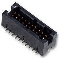
Conn Shrouded Header HDR 40 POS 1.27mm Solder ST SMD Tube
Manufacturer
TE Connectivity
Type
Shrouded Headerr
Series
AMPMODU 50/50 Gridr
Specifications of 5-104655-5
Pitch
1.27 mm
Number Of Rows
2
Number Of Contacts
40
Gender
HDR
Contact Plating
Gold Over Nickel
Termination Method
Solder
Connector Type
Wire To Board
Contact Termination
Solder
No. Of Contacts
40
No. Of Rows
2
Pitch Spacing
1.27mm
Contact Material
Copper
Rohs Compliant
Yes
Product Type
Headers
Stack Height
6.35 mm
Mounting Style
SMD/SMT
Mounting Angle
Vertical
Number Of Positions / Contacts
40
Housing Material
Liquid Crystal Polymer (LCP)
Voltage Rating
30 VAC
Current Rating
1 A to 4 A
Mount Angle
Vertical
Pcb Mount Retention
With
Mating Connector Lock
Without
Hold-down Post Material
Copper Alloy
Hold-down Post Plating
Tin (150) over Nickel (50)
Insulation Resistance (m?)
5,000
Voltage (vac)
30
Dielectric Withstanding Voltage (v)
300
Contact - Rated Current (a)
1 – 4
Solder Tail Contact Plating
Tin-Lead (150)
Mated Stack Height (vertical) (mm [in])
6.35 [0.250]
Number Of Positions
40
Pcb Mount Retention Type
Hold Down Post(s)
Contact Base Material
Phosphor Bronze
Contact Plating, Mating Area, Material
Gold (30)
Underplate Material
Nickel
Connector Style
Plug
Mating Alignment
With
Mating Alignment Type
Keyed
Ul Flammability Rating
UL 94V-0
Housing Color
Black
Rohs/elv Compliance
RoHS compliant, ELV compliant
Lead Free Solder Processes
Reflow solder capable to 245°C, Reflow solder capable to 260°C
Rohs/elv Compliance History
Always was RoHS compliant
Approved Standards
UL E28476, CSA LR7189
Temperature Range (°c)
-65 – +105
Packaging Method
Tube
Lead Free Status / Rohs Status
Details


2
Note: All part numbers are RoHS compliant.
(Soldertail
Length)
Dim. C
.102
2.59
.165
4.19
No. of
Pos.
10
14
16
20
24
26
30
34
40
50
60
10
14
16
20
24
26
34
40
50
1.250 [31.75]
1.450 [36.83]
1.550 [39.37]
1.750 [44.45]
2.050 [52.07]
2.250 [57.15]
2.450 [62.23]
2.750 [69.85]
3.250 [82.55]
3.750 [95.25]
1.250 [31.75]
1.450 [36.83]
1.550 [39.37]
1.750 [44.45]
2.050 [52.07]
2.450 [62.23]
2.750 [69.85]
3.250 [82.55]
1.950[49.53]
1.950[49.53]
A
Dimensions
View for Clarity
[8.89]
[8.89]
Eject Latches
Not Shown in
Top and Side
.350
.350
[0.33]
[8.89
.013
.350
Position #1 Indicator
Position #1 Indicator
1.100 [27.94]
1.200 [30.48]
1.400 [35.56]
1.600 [40.64]
1.900 [48.26]
2.400 [60.96]
2.900 [73.66]
1.100 [27.94]
1.200 [30.48]
1.600 [40.64]
1.900 [48.26]
2.400 [60.96]
[0.33]
[0.33]
+ .005
– .010
+ 0.13
– 0.25
.400 [10.16]
.600 [15.24]
.700 [17.78]
.900 [22.86]
.400 [10.16]
.600 [15.24]
.700 [17.78]
.900 [22.86]
.013
.013
]
B
Pin 2
1-1761693-1
1-1761693-6
Pin Header
[0.63
.025
1761693-3
1761693-8
1761694-3
1761694-9
Latches
without
—
—
—
—
—
—
—
—
—
—
—
—
—
—
± .001
± 0.03
[2.54]
Without Latches
.100
With Latches
]
Pin 1
Recommended PC Board Layout
A
A
B
U
U
U
U
Pin Header with Short Latches
[0.63
.025
(Mates with Receptacles
without Strain Relief)
± .001
± 0.03
Ø .035
[0.89
1-1761685-0
1-1761685-1
1-1761685-3
1-1761685-5
1-1761685-6
1-1761687-1
1-1761687-3
]
1761685-3
1761685-6
1761685-7
1761685-8
1761685-9
1761687-3
1761687-7
1761687-9
± .003
± 0.08
—
—
—
—
—
]
[14.62
[10.64
.576
.419
Part Numbers
[2.54]
± .006
± .006
.100
± 0.15
± 0.15
[20.98
[16.89
.826
.665
[6.40
[2.54]
]
]
.100
.252
Long
Short
± .020
± .020
± 0.51
± 0.51
+ .010
– .004
+ 0.25
– 0.10
Pin Header with Long Latches
]
]
[0.63
.025
Long
Short
(Mates with Receptacles
]
Ø .031
with Strain Relief)
[0.79]
± .001
± 0.03
Max.
1-1761686-1
1-1761686-3
1-1761686-5
1-1761688-1
1-1761688-5
Section U-U
]
1761686-3
1761686-5
1761686-6
1761686-7
1761686-8
1761686-9
1761688-7
1761688-8
1761688-9
—
—
—
—
—
—
C
[
[6.10
± .015
± 0.38
.240
± .010
± 0.25
]
]
Related parts for 5-104655-5
Image
Part Number
Description
Manufacturer
Datasheet
Request
R

Part Number:
Description:
Conn Unshrouded Header HDR 10 POS 2.54mm Solder ST SMD
Manufacturer:
TE Connectivity
Datasheet:

Part Number:
Description:
Conn Shrouded Header HDR 10 POS 2.54mm Solder ST Thru-Hole
Manufacturer:
TE Connectivity
Datasheet:

Part Number:
Description:
Conn Shrouded Header HDR 10 POS 2.54mm Solder ST Thru-Hole
Manufacturer:
TE Connectivity
Datasheet:

Part Number:
Description:
Conn Unshrouded Header HDR 10 POS 2.54mm Solder ST SMD
Manufacturer:
TE Connectivity
Datasheet:

Part Number:
Description:
STACKING CONN, HEADER, 10POS, 1.27MM
Manufacturer:
TE Connectivity
Datasheet:

Part Number:
Description:
Manufacturer:
TE Connectivity
Datasheet:

Part Number:
Description:
Manufacturer:
TE Connectivity
Datasheet:

Part Number:
Description:
Conn Shrouded Header HDR 4 POS 2.54mm Solder ST Thru-Hole
Manufacturer:
TE Connectivity
Datasheet:

Part Number:
Description:
Conn Shrouded Header HDR 3 POS 2.54mm Solder RA Thru-Hole
Manufacturer:
TE Connectivity
Datasheet:

Part Number:
Description:
Conn Shrouded Header HDR 3 POS 2.54mm Solder ST Thru-Hole
Manufacturer:
TE Connectivity
Datasheet:

Part Number:
Description:
Conn Shrouded Header HDR 2 POS 2.54mm Solder ST Thru-Hole Tube
Manufacturer:
TE Connectivity
Datasheet:

Part Number:
Description:
Conn IDC Connector PIN 2 POS 2.54mm IDT ST Cable Mount Strip
Manufacturer:
TE Connectivity
Datasheet:

Part Number:
Description:
Conn IDC Connector RCP 2 POS 2.54mm IDT ST Cable Mount Strip
Manufacturer:
TE Connectivity
Datasheet:

Part Number:
Description:
Conn Shrouded Header HDR 2 POS 2.54mm Solder ST Thru-Hole Tube
Manufacturer:
TE Connectivity
Datasheet:

Part Number:
Description:
Conn Shrouded Header HDR 2 POS 2.54mm Solder ST Thru-Hole Tube
Manufacturer:
TE Connectivity
Datasheet: