104313-2 TE Connectivity, 104313-2 Datasheet - Page 241
104313-2
Manufacturer Part Number
104313-2
Description
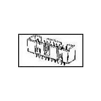
Conn Ejector Header HDR 14 POS 2.54mm Solder ST Thru-Hole
Manufacturer
TE Connectivity
Type
Ejector Headerr
Series
AMP-LATCHr
Datasheet
1.1-102618-8.pdf
(320 pages)
Specifications of 104313-2
Pitch
2.54 mm
Number Of Rows
2
Number Of Contacts
14
Gender
HDR
Contact Plating
Gold Over Nickel
Termination Method
Solder
Connector Type
Wire To Board
Contact Termination
Through Hole
No. Of Contacts
14
No. Of Rows
2
Pitch Spacing
2.54mm
Rohs Compliant
No
Product Line
AMP-LATCH
Profile
Low
Pcb Mounting Orientation
Vertical
Pcb Mount Retention
Without
Mating Connector Lock
Without
Housing Style
4-Sided
Ejection Latches
With
Post Size (mm [in])
0.64 [.025]
Shrouded
Yes
[shrouded] End Dimension (mm [in])
3.81 [0.150]
Current Rating (a)
1
Insulation Resistance (m?)
5,000
Termination Post Length (mm [in])
3.05 [0.120]
Solder Tail Contact Plating
Tin-Lead over Nickel
Header Type
Pin Header
Number Of Positions
14
Centerline, Matrix (mm [in])
2.54 x 2.54 [.100 x .100]
Daisy Chain
With
Preloaded
Yes
Contact Plating, Mating Area, Material
Gold (30)
Contact Shape
Square
Contact Base Material
Copper Alloy
Connector Style
Header - Pin
Mating Alignment Type
Center, Dual Polarizing Bar
Mating Alignment
With
Housing Material
Thermoplastic - GF
Ul Flammability Rating
UL 94V-0
Housing Color
Black
Rohs/elv Compliance
Not ELV/RoHS compliant
Lead Free Solder Processes
Not suitable for lead free processing
Approved Standards
UL E28476, CSA LR7189
Operating Temperature (°c)
-65 – +105
Temperature Rating
Standard


Double-Row
Material
Black thermoplastic, 94V-0 rated
Technical Documents
pages 277, 278
Product Specification
108-25034
Application Specification
114-25026
Catalog 1307819
Revised 8-08
www.tycoelectronics.com
—
are metric equivalents.
Dimensions are in inches and
millimeters unless otherwise
specified. Values in brackets
AMPMODU Interconnection System
Coupling Shrouds for MTE Receptacle Assemblies with Guide Ribs
1
1
Typical Application of Double-Row Coupling Shroud and Mating AMPMODU Products
Note: All part numbers are RoHS compliant.
Mating AMPMODU Double-Row Shrouded Headers must have .318 [8.08] mating post length and .150 [3.81] dimension from centerline
of last post to inside of end shroud wall.
Assemblies with Guide
Ribs (Refer to pages
232, 233 & 235)
Position No. 1
Identification
Receptacle
Dimensions are shown for
reference purposes only.
Specifications subject
to change.
Coupling Shroud
Double-Row
Headers Double-Row, Straight
No. of
Pos.
AMPMODU Shrouded
or Right–Angle Post
10
12
14
16
18
20
22
24
26
28
30
32
34
40
50
8
A
1.085 [27.56]
1.185 [30.10]
1.285 [32.64]
1.385 [35.18]
1.485 [37.72]
1.585 [40.26]
1.685 [42.80]
1.785 [45.34]
1.885 [47.88]
2.185 [55.50]
2.685 [68.20]
.585 [14.86]
.685 [17.40]
.785 [19.94]
.885 [22.48]
.985 [25.02]
Dimension
USA: 1-800-522-6752
Canada: 1-905-470-4425
Mexico: 01-800-733-8926
C. America: 52-55-1106-0803
1
A
Coupling Shroud
Double-Row
1-104500-0
1-104500-1
103681-1
103681-2
103681-3
103681-4
103681-5
104500-1
104500-2
104500-3
104500-4
104500-5
104500-6
104500-7
104500-8
104500-9
South America: 55-11-2103-6000
Hong Kong: 852-2735-1628
Japan: 81-44-844-8013
UK: 44-8706-080-208
[18.67]
.735
(Continued)
241
5
Related parts for 104313-2
Image
Part Number
Description
Manufacturer
Datasheet
Request
R

Part Number:
Description:
Conn Ejector Header HDR 10 POS 2.54mm Solder ST Thru-Hole
Manufacturer:
TE Connectivity
Datasheet:

Part Number:
Description:
Conn Ejector Header HDR 16 POS 2.54mm Solder ST Thru-Hole
Manufacturer:
TE Connectivity
Datasheet:
Part Number:
Description:
Conn Ejector Header HDR 26 POS 2.54mm Solder ST Thru-Hole
Manufacturer:
TE Connectivity
Datasheet:
Part Number:
Description:
Conn Ejector Header HDR 20 POS 2.54mm Solder ST Thru-Hole
Manufacturer:
TE Connectivity
Datasheet:

Part Number:
Description:
Conn Ejector Header HDR 34 POS 2.54mm Solder ST Thru-Hole
Manufacturer:
TE Connectivity
Datasheet:

Part Number:
Description:
High Speed / Modular Connectors 30P HEADER ASSY
Manufacturer:
TE Connectivity
Datasheet:

Part Number:
Description:
High Speed / Modular Connectors REC 6X005P R/A LT B-PLANE HS3
Manufacturer:
TE Connectivity
Datasheet:

Part Number:
Description:
High Speed / Modular Connectors 2MM HM RCPT 50P R/A AU
Manufacturer:
TE Connectivity
Datasheet:

Part Number:
Description:
High Speed / Modular Connectors 2MM HM RCPT 50P R/A AU
Manufacturer:
TE Connectivity
Datasheet:


Part Number:
Description:
Manufacturer:
TE Connectivity
Datasheet:


Part Number:
Description:
Manufacturer:
TE Connectivity
Datasheet:

Part Number:
Description:
Manufacturer:
TE Connectivity
Datasheet:

Part Number:
Description:
Manufacturer:
TE Connectivity
Datasheet: