104313-6 TE Connectivity, 104313-6 Datasheet - Page 238
104313-6
Manufacturer Part Number
104313-6
Description
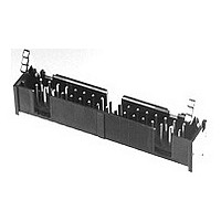
Conn Ejector Header HDR 34 POS 2.54mm Solder ST Thru-Hole
Manufacturer
TE Connectivity
Type
Ejector Headerr
Datasheet
1.1-102618-8.pdf
(320 pages)
Specifications of 104313-6
Pitch
2.54 mm
Number Of Rows
2
Number Of Contacts
34
Gender
HDR
Contact Plating
Gold
Termination Method
Solder
Product Line
AMP-LATCH
Profile
Low
Pcb Mounting Orientation
Vertical
Pcb Mount Retention
Without
Mating Connector Lock
Without
Housing Style
4-Sided
Ejection Latches
With
Post Size (mm [in])
0.64 [.025]
Shrouded
Yes
[shrouded] End Dimension (mm [in])
3.81 [0.150]
Current Rating (a)
1
Insulation Resistance (m?)
5,000
Termination Post Length (mm [in])
3.05 [0.120]
Solder Tail Contact Plating
Tin-Lead over Nickel
Header Type
Pin Header
Number Of Positions
34
Centerline, Matrix (mm [in])
2.54 x 2.54 [.100 x .100]
Daisy Chain
With
Preloaded
Yes
Contact Plating, Mating Area, Material
Gold (30)
Contact Shape
Square
Contact Base Material
Copper Alloy
Connector Style
Header - Pin
Mating Alignment Type
Center, Dual Polarizing Bar
Mating Alignment
With
Housing Material
Thermoplastic - GF
Ul Flammability Rating
UL 94V-0
Housing Color
Black
Rohs/elv Compliance
Not ELV/RoHS compliant
Lead Free Solder Processes
Not suitable for lead free processing
Approved Standards
UL E28476, CSA LR7189
Operating Temperature (°c)
-65 – +105
Temperature Rating
Standard


5
238
Preassembled housings in strip
form are available in positions
2 thru 12. For ease of handling,
positions 2 thru 5 are recom-
mended when using the
Tyco Electronics Manual Pistol
Grip Tool.
Material and Finish
Housing — Black thermoplastic,
94V-0 rated
Contacts — Phosphor Bronze,
plated as follows:
Plating A — Duplex plated .000030
[0.00076] gold on contact area, .000050
[0.00127] min. tin in crimp area, with
entire contact underplated .000050
[0.00127] nickel
Plating B — Duplex plated .000015
[0.00038] gold on contact area, .000050
[0.00127] min. tin in crimp area, with
entire contact underplated .000050
[0.00127] nickel
Plating C — .000100 [0.00254] tin
over .000050 [0.00127] nickel on entire
contact
Note: Insulation displacement contacts
accept an insulation diameter of .030 [0.76]
min. to .054 [1.37] max. with an insula-
tion wall thickness of .015 [0.38] max.
Related Product Data
Mateable AMPMODU MTE Products
(with Pin Assembly Installed in
Panel Mount Pin Shroud) —
pages 242, 243
Receptacle Assemblies
(Polarized/Latching) —
pages 230, 231
Receptacle Assemblies with Guide
Ribs (installed in Single Row
Coupling Shroud) — pages 232, 233,
235, 240
Interchangeable Crimp Contacts —
page 254
Application Tooling — page 273
Performance Specifications —
page 225
Technical Documents
pages 277, 278
Product Specification
108-25034
Application Specification
114-25026
Catalog 1307819
Revised 8-08
www.tycoelectronics.com
—
are metric equivalents.
Dimensions are in inches and
millimeters unless otherwise
specified. Values in brackets
AMPMODU Interconnection System
MTE Pin Assemblies—Guide Ribs,
Single-Row, .100 [2.54] Centerline
Typ.
B
Dimensions are shown for
reference purposes only.
Specifications subject
to change.
[2.54] Typ.
.100
A
USA: 1-800-522-6752
Canada: 1-905-470-4425
Mexico: 01-800-733-8926
C. America: 52-55-1106-0803
Pin Contacts
(See Note 1)
[2.49]
.098
Position No. 1 Indicator
[28.45]
1.120
(Farside)
South America: 55-11-2103-6000
Hong Kong: 852-2735-1628
Japan: 81-44-844-8013
UK: 44-8706-080-208
[15.24]
[13.21]
.600
.520
Related parts for 104313-6
Image
Part Number
Description
Manufacturer
Datasheet
Request
R

Part Number:
Description:
Conn Ejector Header HDR 10 POS 2.54mm Solder ST Thru-Hole
Manufacturer:
TE Connectivity
Datasheet:

Part Number:
Description:
Conn Ejector Header HDR 16 POS 2.54mm Solder ST Thru-Hole
Manufacturer:
TE Connectivity
Datasheet:
Part Number:
Description:
Conn Ejector Header HDR 26 POS 2.54mm Solder ST Thru-Hole
Manufacturer:
TE Connectivity
Datasheet:
Part Number:
Description:
Conn Ejector Header HDR 14 POS 2.54mm Solder ST Thru-Hole
Manufacturer:
TE Connectivity
Datasheet:
Part Number:
Description:
Conn Ejector Header HDR 20 POS 2.54mm Solder ST Thru-Hole
Manufacturer:
TE Connectivity
Datasheet:

Part Number:
Description:
High Speed / Modular Connectors 30P HEADER ASSY
Manufacturer:
TE Connectivity
Datasheet:

Part Number:
Description:
High Speed / Modular Connectors REC 6X005P R/A LT B-PLANE HS3
Manufacturer:
TE Connectivity
Datasheet:

Part Number:
Description:
High Speed / Modular Connectors 2MM HM RCPT 50P R/A AU
Manufacturer:
TE Connectivity
Datasheet:

Part Number:
Description:
High Speed / Modular Connectors 2MM HM RCPT 50P R/A AU
Manufacturer:
TE Connectivity
Datasheet:


Part Number:
Description:
Manufacturer:
TE Connectivity
Datasheet:


Part Number:
Description:
Manufacturer:
TE Connectivity
Datasheet:

Part Number:
Description:
Manufacturer:
TE Connectivity
Datasheet:

Part Number:
Description:
Manufacturer:
TE Connectivity
Datasheet: