85923-2 TE Connectivity, 85923-2 Datasheet - Page 7
85923-2
Manufacturer Part Number
85923-2
Description
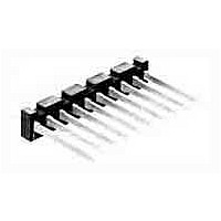
Conn Unshrouded Header HDR 2 POS 3.96mm Solder ST Thru-Hole
Manufacturer
TE Connectivity
Type
Unshrouded Headerr
Datasheet
1.87986-4.pdf
(42 pages)
Specifications of 85923-2
Pitch
3.96 mm
Number Of Rows
1
Number Of Contacts
2
Gender
HDR
Contact Plating
Gold Over Nickel
Termination Method
Solder
Product Type
Connector
Connector Type
Header
Mount Angle
Vertical
Keyed
Yes
Mating Post Length (mm [in])
19.05 [0.750]
Contact - Rated Current (a)
5
Dielectric Withstanding Voltage (v)
1200
Contact Resistance (m?)
12
Insulation Resistance (m?)
5,000
Termination End Plating
Gold (30) over Nickel (50)
Number Of Positions
2
Centerline (mm [in])
3.96 [0.156]
Number Of Keys
1
Contact Type
Pin
Contact Plating, Mating Area, Material
Gold (30)
Contact Base Material
Brass
Connector Style
Plug
Housing Material
PBT - GF
Housing Color
Black
Ul Flammability Rating
UL 94V-0
Rohs/elv Compliance
RoHS compliant, ELV compliant
Lead Free Solder Processes
Wave solder capable to 240°C
Rohs/elv Compliance History
Always was RoHS compliant
Approved Standards
UL E28476, CSA LR16455
Temperature Range (°c)
-65 – +105


Vertical and Horizontal
Board Mount
Related Product Data
Recommended Board Layout for
Type C — page 288
Mates with —
Machine Applied Posts — page 294
Headers — pages 295-297
Application Tooling —
pages 300-304
Performance Specifications —
page 305
Technical Documents
page 305
Keying Plug
Catalog 1307819
Revised 8-08
www.tycoelectronics.com
Use in Board Mount Receptacles
Part No. 86181-2
Post Entry
Post Entry
Horizontal
Post Entry
Bottom
Type A
Type B
Type C
Top
—
are metric equivalents.
Dimensions are in inches and
millimeters unless otherwise
specified. Values in brackets
AMPMODU Interconnection System
Mod I Receptacles, Board Mount, .031 x .062 [0.79 x 1.57] Centerline
Receptacle Styles
Recommended Board Layout for Receptacle Assemblies
and Individual Receptacles (Type A and B)
Note: All part numbers are RoHS compliant.
J-Receptacle centers may vary depending on requirements. For individual receptacles, minimum nominal centerline
spacing between adjacent receptacles is .150 [3.81]; for receptacle assemblies, centerline spacing between adjacent
receptacles is .156 [3.96]. The .003 [0.08] tolerances are not to accumulate over length of board. For solder mask, see
Tyco Electronics Instruction Sheet 408-7411.
Note: Drawings depict normal use of the contact in a one or two-sided circuit board. When using plated thru-holes,
refer to Tyco Electronics Engineering Report ER-001 and Tyco Electronics Instruction Sheet 408-7411. For solder
mask, see Tyco Electronics Instruction Sheet 408-7411.
Dimensions are shown for
reference purposes only.
Specifications subject
to change.
[7.62]
.300
[0.99]
.093
Max.
[3.18]
J
.125
[1.40]
[3.18]
.055
Min.
.125
[±0.08]
±.003
Max.
(Post Entry Type A or B)
USA: 1-800-522-6752
Canada: 1-905-470-4425
Mexico: 01-800-733-8926
C. America: 52-55-1106-0803
2J
Round Hole
[±0.08]
±.003
[3.18]
.125
Max.
[2.54]
.100
[3.18±0.05]
.125±.002
Min.
[0.99]
.093
[7.62]
.300
Max.
South America: 55-11-2103-6000
Hong Kong: 852-2735-1628
Japan: 81-44-844-8013
UK: 44-8706-080-208a
[7.62]
.300
[2.36]
.093
Max.
[3.18]
.125
Max.
285
7
Related parts for 85923-2
Image
Part Number
Description
Manufacturer
Datasheet
Request
R

Part Number:
Description:
Conn Unshrouded Header HDR 4 POS 3.96mm Solder ST Thru-Hole
Manufacturer:
TE Connectivity
Datasheet:

Part Number:
Description:
High Speed / Modular Connectors 30P HEADER ASSY
Manufacturer:
TE Connectivity
Datasheet:

Part Number:
Description:
High Speed / Modular Connectors REC 6X005P R/A LT B-PLANE HS3
Manufacturer:
TE Connectivity
Datasheet:

Part Number:
Description:
High Speed / Modular Connectors 2MM HM RCPT 50P R/A AU
Manufacturer:
TE Connectivity
Datasheet:

Part Number:
Description:
High Speed / Modular Connectors 2MM HM RCPT 50P R/A AU
Manufacturer:
TE Connectivity
Datasheet:


Part Number:
Description:
Manufacturer:
TE Connectivity
Datasheet:


Part Number:
Description:
Manufacturer:
TE Connectivity
Datasheet:

Part Number:
Description:
Manufacturer:
TE Connectivity
Datasheet:

Part Number:
Description:
Manufacturer:
TE Connectivity
Datasheet: