PM54-820K Bourns Inc., PM54-820K Datasheet - Page 87
PM54-820K
Manufacturer Part Number
PM54-820K
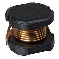
Description
Power Inductors 82uH 10%
Manufacturer
Bourns Inc.
Specifications of PM54-820K
Inductance
82 uH
Tolerance
10 %
Maximum Dc Current
0.58 Amp
Maximum Dc Resistance
0.6 Ohms
Self Resonant Frequency
10 MHz
Shielding
Unshielded
Termination Style
SMD/SMT
Inductance Tolerance
± 10%
Dc Resistance Max
0.6ohm
Dc Current Rating
580mA
Core Material
Ferrite
Inductor Case Style
SMD
No. Of Pins
2
Lead Free Status / RoHS Status
Lead free / RoHS Compliant
Available stocks
Company
Part Number
Manufacturer
Quantity
Price
Company:

Part Number:
PM54-820K-RC
Manufacturer:
BOURNS
Quantity:
30 000
Part Number:
PM54-820K-RC
Manufacturer:
BOURNS/伯恩斯
Quantity:
20 000


Special Features
• High current capacity
• Magnetic shielded for low radiation
• Ferrite bobbin core
• Low core loss for high frequency power applications
• Compact size
• Large terminal surface for good PCB bonding
• Easy access for refl ow soldering inspection
• Operating temperature -30 to +100 °C
• Tape & reel packaged 1500/reel
Typical Applications
• Desktop, notebook computers, servers
• Network hubs, bridges, routers
• xDSL, PBX base stations
• PDAs, MP3 players
• Digital TVs, DVDs, cable modems, DSS set-top boxes
• Battery chargers
• High frequency wireless communication devices
• Electronic game devices
• Industrial electronics
Notes
* Current to cause 10 % of inductance
drop, or 40 °C temperature rise
Tel. (877) 426-8767 • Fax (951) 781-5006
Shielded, SMT Power Inductors
www.bourns.com
For RoHS compliant version, add “-RC” to part number.
6.2
Part
Number
PM63SB-100M
PM63SB-120M
PM63SB-150M
PM63SB-180M
PM63SB-220M
PM63SB-270M
PM63SB-330L
PM63SB-390L
PM63SB-470L
PM63SB-560L
PM63SB-680L
Dimensions: mm
Tolerance: -/+ 0.3
5.6
± 15 %
±20 %
L (μH)
10
12
15
18
22
27
33
39
47
56
68
1.5 Ref.
3.2
PM63SB Series
2.52MHz
2.52MHz
2.52MHz
2.52MHz
2.52MHz
2.52MHz
2.52MHz
2.52MHz
2.52MHz
2.52MHz
2.52MHz
Freq.
Test
1.7
(MHz)
Typ.
SRF
35
32
29
26
23
20
18
17
15
14
12
Pad Layout
R 1
5.5
Max.
DCR
0.14
0.16
0.18
0.25
0.32
0.36
0.41
0.47
0.51
0.72
0.82
(Ω)
I, DC*
1.00
0.94
0.86
0.78
0.76
0.64
0.61
0.53
0.50
0.46
0.42
5.17
(A)
6.2
Related parts for PM54-820K
Image
Part Number
Description
Manufacturer
Datasheet
Request
R

Part Number:
Description:
Power Inductors 120uH
Manufacturer:
Bourns Inc.
Datasheet:

Part Number:
Description:
Power Inductors 120uH 10%
Manufacturer:
Bourns Inc.
Datasheet:
Part Number:
Description:
Power Inductors 150uH 10%
Manufacturer:
Bourns Inc.
Datasheet:

Part Number:
Description:
POWER INDUCTOR 100UH 520MA 10% 9MHZ
Manufacturer:
Bourns Inc.
Datasheet:
Part Number:
Description:
Power Inductors 56uH 10%
Manufacturer:
Bourns Inc.
Datasheet:
Part Number:
Description:
Power Inductors 47uH 15%
Manufacturer:
Bourns Inc.
Datasheet:
Part Number:
Description:
Power Inductors 47uH .72A 15% SMD
Manufacturer:
Bourns Inc.
Datasheet:
Part Number:
Description:
Power Inductors 33uH 15%
Manufacturer:
Bourns Inc.
Datasheet:
Part Number:
Description:
Power Inductors 220uH 10%
Manufacturer:
Bourns Inc.
Datasheet:
Part Number:
Description:
Power Inductors 22uH 20%
Manufacturer:
Bourns Inc.
Datasheet:

Part Number:
Description:
Manufacturer:
Bourns, Inc.
Datasheet:
Part Number:
Description:
11mm Potentiometer
Manufacturer:
Bourns, Inc.
Datasheet: