R1G133-AA17-02 EBM-Papst Industries Inc, R1G133-AA17-02 Datasheet - Page 6
R1G133-AA17-02
Manufacturer Part Number
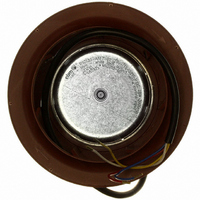
R1G133-AA17-02
Description
IMPELLER MOTORIZD 133X91MM 24VDC
Manufacturer
EBM-Papst Industries Inc
Series
R1G133AAr
Type
Impellersr
Datasheets
1.R1G133-AA17-02.pdf
(5 pages)
2.R1G133-AA17-02.pdf
(9 pages)
3.R1G133-AA17-02.pdf
(1 pages)
4.R1G133-AA17-02.pdf
(1 pages)
Specifications of R1G133-AA17-02
Current Type
DC
Supply Voltage
24 V
Bearing Type
Ball
Termination Style
63 dB(A)
Noise
63 dB(A)
Fan Type
Motorized Impellers
Size / Dimension
Round - 133mm Dia x 91mm W
Voltage - Rated
24VDC
Power (watts)
28.0W
Features
PWM Control; Speed Sensor (Tach)
Rpm
3900 RPM
Air Flow
212.0 CFM (6.00m³/min)
Termination
4 Wire Leads
Weight
1.4 lbs (635g)
Current Rating
1.30A
Voltage Range
16 ~ 28VDC
Operating Temperature
-13 ~ 140°F (-25 ~ 60°C)
Airflow
212 CFM
Speed
3900 RPM
Frame Dimensions (mm)
133 mm x 91 mm
Power Rating
28 W
External Depth
91mm
External Diameter
133mm
Flow Rate
212CFM
Noise Rating
63dBA
Power Connection Type
Lead Wires
Brand/series
R1G133AA Series
Diameter, Outer
133 mm
Dimensions
5.24"Dia.x3.58"W
Material, Impeller
Plastic
Noise Level
63 dBA
Power, Rating
28 W
Size
Φ 133 mm (5.24") Backward Curve
Special Features
Tachometer
Standards
UL Listed, CSA Certified, VDE Approval
Temperature, Ambient
60 °C (Max.)
Temperature, Operating, Maximum
+60 °C
Voltage, Rating
24 VDC
Diameter
133mm
Flow Rate - Imperial
212CFM
Rohs Compliant
Yes
Lead Free Status / RoHS Status
Lead free / RoHS Compliant
Static Pressure
-
Lead Free Status / Rohs Status
Lead free / RoHS Compliant
Other names
381-1154


4. CONNECTION AND START-UP
4.1 Connecting the mechanical system
4.2 Connecting the electrical system
4.2.1 Prerequisites
4.3 Connection of the cables
External leads are brought out of device.
Item no.: 50115-5-9970 · Revision status: KM70943 · Print-out on 09.06.10 · Created by A. Kehm (VM---) · Page 6 of 9
ebm-papst Mulfingen GmbH & Co. KG · Bachmühle 2 · 74673 Mulfingen · Phone: +49 7938 81-0 · Fax: +49 7938 81-110 · www.ebmpapst.com · info1@de.ebmpapst.com
R1G133-AA17-02
Install the device according to your application.
Check whether the data on the type plate agree with the connection
data.
Before connecting the device, ensure that the supply voltage matches
the operating voltage of the device.
Only use cables designed for current according to the type plate.
Connect the lines according to your application. When doing so,
observe chapter 4.4 Connection diagram.
CAUTION
Cutting and crushing hazard when removing the fan
from the packaging
CAUTION
Electrical voltage
The fan is a built-in component and features no electrically
isolating switch.
NOTE
Water penetration into leads or wires
Water enters at the cable end on the customers side and can
damage the device.
Operate the device with a safely isolated power pack.
Carefully seize the impeller to lift the device out of its
packaging. Make sure to avoid any shock.
Wear safety shoes and cut-resistant safety gloves.
Only connect the fan to circuits that can be switched off with
an all-pole separating switch.
When working on the fan, you must switch off the
installation/machine in which the fan is installed and secure it
from being switched on again.
Make sure that the cable end is connected in a dry
environment.
Operating instructions
Related parts for R1G133-AA17-02
Image
Part Number
Description
Manufacturer
Datasheet
Request
R

Part Number:
Description:
IMPELLER MOTORIZD 133X91MM 48VDC
Manufacturer:
EBM-Papst Industries Inc
Datasheet:

Part Number:
Description:
IMPELLER MTRZD 133X60MM 48VDC
Manufacturer:
EBM-Papst Industries Inc
Datasheet:
Part Number:
Description:
IMPELLER MTRZD 133X60MM 12VDC
Manufacturer:
EBM-Papst Industries Inc
Datasheet:

Part Number:
Description:
DC MOTORIZED IMPELLER, 133 X 91MM, 12V
Manufacturer:
EBM-Papst Industries Inc
Datasheet:
Part Number:
Description:
DC Backward-Curved Motorized Impeller
Manufacturer:
EBM-Papst Industries Inc

Part Number:
Description:
FAN EXHAUST 119 X 25MM 230VAC
Manufacturer:
EBM-Papst Industries Inc
Datasheet:

Part Number:
Description:
FAN TUBEAXIAL 92X38MM 115VAC
Manufacturer:
EBM-Papst Industries Inc
Datasheet:

Part Number:
Description:
FAN EXHAUST 92 X 38MM 115VAC
Manufacturer:
EBM-Papst Industries Inc
Datasheet:

Part Number:
Description:
FAN TUBEAXIAL 92X25MM 115VAC
Manufacturer:
EBM-Papst Industries Inc
Datasheet:
Part Number:
Description:
FAN EXHAUST 119 X 25MM 230VAC
Manufacturer:
EBM-Papst Industries Inc
Datasheet:

Part Number:
Description:
FAN TUBEAXIAL 92X38MM 230VAC
Manufacturer:
EBM-Papst Industries Inc
Datasheet:

Part Number:
Description:
FAN 92 X 32MM 12VDC
Manufacturer:
EBM-Papst Industries Inc
Datasheet:

Part Number:
Description:
FAN TUBEAXIAL 40X20MM 5VDC
Manufacturer:
EBM-Papst Industries Inc
Datasheet:

Part Number:
Description:
AC Tubeaxial Fan
Manufacturer:
EBM-Papst Industries Inc
Datasheet: