PM105-150M Bourns Inc., PM105-150M Datasheet
PM105-150M
Manufacturer Part Number
PM105-150M
Description
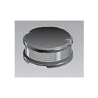
Power Inductors 15uH 20%
Manufacturer
Bourns Inc.
Series
PM105r
Datasheet
1.PM105-101K-RC.pdf
(2 pages)
Specifications of PM105-150M
Core Material
Ferrite DR
Test Frequency
2.52 MHz
Inductance
15 uH
Tolerance
20 %
Maximum Dc Current
2.25 Amps
Maximum Dc Resistance
0.08 Ohms
Self Resonant Frequency
19 MHz
Q Minimum
30
Dimensions
9.8 mm Dia. x 5.8 mm H
Shielding
Unshielded
Operating Temperature Range
- 40 C to + 125 C
Termination Style
SMD/SMT
Dc Resistance Max
0.08ohm
Dc Current Rating
2.27A
Ferrite Case Style
SMD
Inductor Type
Power
Body Material
Ferrite
No. Of Pins
2
Lead Free Status / RoHS Status
Lead free / RoHS Compliant


*RoHS Directive 2002/95/EC Jan 27 2003 including Annex.
Specifi cations are subject to change without notice.
Customers should verify actual device performance in their specifi c applications
Bourns Part No.
PM105-100M-RC
PM105-120M-RC
PM105-150M-RC
PM105-180M-RC
PM105-220M-RC
PM105-270K-RC
PM105-330K-RC
PM105-390K-RC
PM105-470K-RC
PM105-560K-RC
PM105-680K-RC
PM105-820K-RC
PM105-101K-RC
PM105-121K-RC
PM105-151K-RC
PM105-181K-RC
PM105-221K-RC
PM105-271K-RC
PM105-331K-RC
PM105-391K-RC
PM105-471K-RC
PM105-561K-RC
PM105-681K-RC
PM105-821K-RC
Typical Part Marking
Electrical Specifi cations
START
Inductance 1 kHz
101
(µH)
100
120
150
180
220
270
330
390
470
560
680
820
10
12
15
18
22
27
33
39
47
56
68
82
FINISH
Tol. %
± 20
± 20
± 20
± 20
± 20
± 10
± 10
± 10
± 10
± 10
± 10
± 10
± 10
± 10
± 10
± 10
± 10
± 10
± 10
± 10
± 10
± 10
± 10
± 10
Ref.
30
30
30
30
25
25
25
20
20
20
15
15
15
15
15
12
12
12
12
12
12
12
12
10
Q
Frequency
(MHz)
0.796
0.796
0.796
0.796
0.796
0.796
0.796
0.796
0.796
0.796
0.796
0.796
Features
■
■
■
■
Test
2.52
2.52
2.52
2.52
2.52
2.52
2.52
2.52
2.52
2.52
2.52
2.52
PM105 Series - SMD Power Inductor
Electrical Schematic
Formerly
Available in E12 series
Small design of only 9.8 mm maximum
diameter
RoHS compliant*
(MHz)
SRF
Min.
9.0
8.0
7.5
7.0
6.0
5.2
5.0
4.5
4.0
3.8
3.5
3.2
3.0
2.5
2.3
2.1
2.0
21
20
16
15
13
11
10
J. W .Miller
0.060
0.070
0.080
0.090
RDC
0.10
0.11
0.12
0.14
0.17
0.19
0.22
0.25
0.35
0.40
0.47
0.63
0.73
0.97
1.15
1.30
1.48
1.90
2.25
2.55
(Ω)
model
I rms
Max.
2.60
2.45
2.25
2.15
1.95
1.75
1.50
1.35
1.25
1.15
1.10
1.00
0.97
0.89
0.78
0.72
0.66
0.57
0.52
0.48
0.42
0.33
0.28
0.24
(A)
I sat
5.10
4.50
4.00
3.80
3.50
3.40
2.90
2.60
2.30
2.10
2.00
1.90
1.70
1.50
1.40
1.30
1.10
1.00
0.85
0.80
0.80
0.66
0.65
0.56
Typ.
(A)
Applications
■
■
Test Frequency ............................. 1 KHz
Test Voltage .......................................1 V
Refl ow Soldering .. 230 °C, 50 sec. max.
Operating Temperature
Storage Temperature .. -40 °C to +125 °C
Resistance to Soldering Heat
Core ................................Ferrite DR core
Wire ....................Enameled copper wire
Terminal ................................... Ag/Ni/Sn
Rated Current
Temperature Rise
Packaging .................... 500 pcs. per reel
Input/output of DC/DC converters
Power supplies for:
• Portable communication equipment
• Camcorders
• LCD TVs
• Car radios
General Specifi cations
Materials
Recommended Layout
Product Dimensions
............................... -40 °C to +125 °C
.................................260 °C for 5 sec.
..................Ind. drop 10 % typ. at Isat
......................40°C max. at rated Irms
(.394)
10.0
MAX.
DIMENSIONS:
(Temperature rise included)
(.386)
(.394)
10.0
9.8
MAX.
MAX.
(INCHES)
(.114)
2.9
MM
TYP.
(.386)
9.8
(.228)
5.8
(.110)
MAX.
2.8
MAX.
MAX.
Related parts for PM105-150M
Image
Part Number
Description
Manufacturer
Datasheet
Request
R

Part Number:
Description:
Power Inductors 270uH 10%
Manufacturer:
Bourns Inc.
Datasheet:
Part Number:
Description:
Power Inductors 120uH 10%
Manufacturer:
Bourns Inc.
Datasheet:
Part Number:
Description:
Power Inductors 150uH 10%
Manufacturer:
Bourns Inc.
Datasheet:
Part Number:
Description:
Power Inductors 100uH 10%
Manufacturer:
Bourns Inc.
Datasheet:

Part Number:
Description:
POWER INDUCTOR, 82UH, 1A, 10%, 8MHZ
Manufacturer:
Bourns Inc.
Datasheet:
Part Number:
Description:
INDUCTOR, 470UH, 420MA, 10%, 2.5MHz
Manufacturer:
Bourns Inc.
Datasheet:
Part Number:
Description:
INDUCTOR, 680UH, 280MA, 10%, 2.1MHz
Manufacturer:
Bourns Inc.
Datasheet:
Part Number:
Description:
Power Inductors 330uH 10%
Manufacturer:
Bourns Inc.
Datasheet:
Part Number:
Description:
Power Inductors 560uH 10%
Manufacturer:
Bourns Inc.
Datasheet:
Part Number:
Description:
Power Inductors 220uH 10%
Manufacturer:
Bourns Inc.
Datasheet:

Part Number:
Description:
Manufacturer:
Bourns, Inc.
Datasheet:
Part Number:
Description:
11mm Potentiometer
Manufacturer:
Bourns, Inc.
Datasheet:
PM105-150M Summary of contents
Page 1
... Electrical Specifi cations Inductance 1 kHz Q Bourns Part No. (µH) Tol. % Ref. PM105-100M-RC 10 ± PM105-120M-RC 12 ± PM105-150M-RC 15 ± PM105-180M-RC 18 ± PM105-220M-RC 22 ± PM105-270K-RC 27 ± PM105-330K-RC 33 ± PM105-390K-RC 39 ± PM105-470K-RC 47 ± PM105-560K-RC 56 ± PM105-680K-RC 68 ± PM105-820K-RC 82 ± PM105-101K-RC 100 ± PM105-121K-RC 120 ± 10 ...
Page 2
... PM105 Series - SMD Power Inductor Packaging Specifi cations 2.0 ± 0.5 330 (.079 ± .020) 30.4 (12.992) (1.20) DIA. 13.0 ± 0.5 21 ± 0.8 (.512 ± .020) (.827 ± .039) DIA. 13.0 ± 0.5 DIA. (.512 ± .020) 26 (1.024) 24 (.945) ...