2519B-EP11-BGS5G Aavid Thermalloy, 2519B-EP11-BGS5G Datasheet - Page 2
2519B-EP11-BGS5G
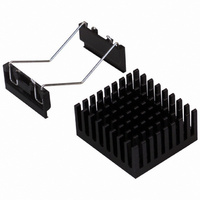
Manufacturer Part Number
2519B-EP11-BGS5G
Description
HEATSINK BGA W/CLIP
Manufacturer
Aavid Thermalloy
Datasheet
1.374424B00035G.pdf
(6 pages)
Specifications of 2519B-EP11-BGS5G
Package Cooled
BGA
Attachment Method
Clip
Outline
34.50mm x 31.40mm
Height
0.62" (15.75mm)
Power Dissipation @ Temperature Rise
1W @ 20°C
Thermal Resistance @ Forced Air Flow
6.3°C/W @ 200 LFM
Thermal Resistance @ Natural
19.7°C/W
Lead Free Status / RoHS Status
Lead free / RoHS Compliant
Other names
2519B-EP11-BGS5
HS309
HS309


1
SOLDER ANCHOR ATTACHMENT METHOD
** Heat Sinks for Flip Chip includes foam pad around perimeter.
Part Number
374024B60023
374124B60023
374224B60023
374324B60023
374424B60023
374524B60023
10-5634-01**
10-THMA-01**
374624B60024
374724B60024
374824B60024
10-BRD2-01**
10-BRD1-01**
10-BRD1-03**
10-BRD1-04**
10-BRD1-05**
10-BRD1-07**
374924B60024
375024B60024
375124B60024
10-CLS1-01**
10-CLS2-01**
* See bottom of page 4 for information on how to use this table
Refer to page 4 for PCB hole patterns
This stabilizes the part so heat sink doesn’t move.
Copyright © Aavid Thermalloy, LLC. April 2002
Solder Anchor Sold Separately
Part # D057
Solder anchors must be soldered to PCB
prior to attaching the heat sink clip
Consult P.C. Board Hole Pattern for number required
Width Length Height *θ n
23.0
23.0
23.0
27.0
27.0
27.0
31.0
31.0
35.0
35.0
35.0
35.7
37.5
37.5
37.5
37.5
37.5
40.0
40.0
40.0
42.3
42.3
23.0
23.0
23.0
27.0
27.0
27.0
34.9
34.9
35.0
35.0
35.0
37.3
37.5
37.5
37.5
37.5
37.5
40.0
40.0
40.0
42.3
42.3
FOR ADDITIONAL TECHNICAL INFORMATION VISIT OUR WEB SITE AT WWW.AAVIDTHERMALLOY.COM/BGA
ITEMS SHOWN IN RED ARE AVAILABLE FROM AAVID THERMALLOY’S AUTHORIZED DISTRIBUTORS
10.0
18.0
25.0
10.0
18.0
25.0
23.0
35.0
10.0
18.0
25.0
23.0
23.0
23.0
23.0
23.0
23.0
10.0
18.0
25.0
23.0
35.0
40.0
23.4
19.7
30.6
20.3
16.5
11.5
10.7
23.4
15.3
12.0
11.5
10.1
10.1
10.1
10.1
10.1
20.3
12.2
10.3
8.8
8.3
11.69
7.39
6.37
9.35
6.46
5.47
4.20
3.95
7.55
5.15
4.27
4.20
3.83
3.83
3.83
3.83
3.83
6.46
4.34
3.83
3.51
3.44
*θ f *Finish
N
N
N
B
B
B
B
B
B
B
B
B
B
B
B
B
B
B
B
B
B
B
G
G
A
A
A
A
A
A
H
H
B
B
B
B
B
B
B
B
B
B
I
I
Corporate Office: Concord, NH • USA
FEATURES AND BENEFITS
• New unique wire clip design allows for complete
• Configurations are available for a wide
• Minimal PC Board real estate is required for
• Solder Anchors provide the most rugged
• Each Heat Sink utilizes a phase change pad as
H
reworkability after assembly without damage
to the BGA package or PC Board
range of BGA package sizes
mounting
mounting in the industry
the interface for optimal thermal performance.
Drawing represents heat sink part numbers
10-BRD1-03 and 10-BRD1-05 that require 4 solder anchors
Drawing represents those heat sinks requiring 2 solder anchors
H
W
W
Tel: (603)224-9988
L
L
Related parts for 2519B-EP11-BGS5G
Image
Part Number
Description
Manufacturer
Datasheet
Request
R

Part Number:
Description:
Heatsink black, extrusion+Pins; 38mm cut;
Manufacturer:
Aavid Thermalloy
Part Number:
Description:
Heatsink extrusion;custom L:150mm;27x50mm;black;
Manufacturer:
Aavid Thermalloy
Part Number:
Description:
Heatsink custom 0S507 extrusion profile cut to length 100mm, black anodi
Manufacturer:
Aavid Thermalloy
Part Number:
Description:
Heatsink custom cut 80mm;black anodized; WxH:30x47.2mm; w/o pad
Manufacturer:
Aavid Thermalloy
Part Number:
Description:
Heatsink extrusion;custom L:100mm;39x31.50mm;black;
Manufacturer:
Aavid Thermalloy
Part Number:
Description:
Heatsink custom 0S515 extrusion cut to length 100mm, black anodise
Manufacturer:
Aavid Thermalloy
Part Number:
Description:
Heatsink extrusion;custom L:100mm;40x75mm;black;
Manufacturer:
Aavid Thermalloy
Part Number:
Description:
Heatsink extrusion;custom L:50mm;40x75mm;black;
Manufacturer:
Aavid Thermalloy
Part Number:
Description:
Heatsink extrusion;custom L:100mm;black;
Manufacturer:
Aavid Thermalloy
Part Number:
Description:
Heatsink extrusion;custom L:150mm;black;
Manufacturer:
Aavid Thermalloy
Part Number:
Description:
Heatsink extrusion;custom L:50mm;black;
Manufacturer:
Aavid Thermalloy
Part Number:
Description:
Heatsink extrusion;custom L:100mm;27x60mm black;
Manufacturer:
Aavid Thermalloy
Part Number:
Description:
Heatsink extrusion;custom L:50mm;27x60mm black;
Manufacturer:
Aavid Thermalloy
Part Number:
Description:
Heatsink extrusion;custom L:150mm;49.50x85.50mm black;
Manufacturer:
Aavid Thermalloy