0400FA15A0400E Johanson Technology Inc, 0400FA15A0400E Datasheet
0400FA15A0400E
Specifications of 0400FA15A0400E
712-1112-2


Related parts for 0400FA15A0400E

0400FA15A0400E Summary of contents
Page 1
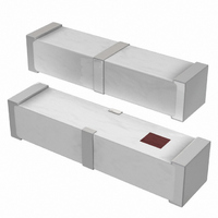
... Frequency Ceramic Solutions" 1.575 GHz Multilayer GPS Chip Antenna Detail Specification: 10/30/08 General Specifications Part Number 1575AT54A0010 Frequency Range 1570 - 1580 Mhz Peak Gain 1.3 dBi typ. (YZ-Total) Average Gain -0.7 dBi typ. (YZ-Total) Return Loss 9.5 dB min. Bulk Packaging Style T & ...
Page 2
... Frequency Ceramic Solutions" 1.575 GHz Multilayer GPS Chip Antenna Detail Specification: 10/30/08 Mounting Considerations Matching circuit and component values will be different, depending on PCB layout *Line width should be designed to provide 50 Ω impedance matching characteristics. a) Without Matching Circuits Ground ) ) ) ) GND Via ) Feeding line ...
Page 3
... Frequency Ceramic Solutions" 1.575 GHz Multilayer GPS Chip Antenna Detail Specification: 10/30/08 Return Loss - Without Matching Circuits 0 -10 -20 -30 1.0 1 1.4 1.6 1.8 freq, GHz www.johansontechnology.com 4001 Calle Tecate • Camarillo, CA 93012 • TEL 805.389.1166 FAX 805.389.1821 2008 Johanson Technology, Inc. All Rights Reserved ...
Page 4
... Frequency Ceramic Solutions" 1.575 GHz Multilayer GPS Chip Antenna Detail Specification: 10/30/08 Typical Electrical Characteristics (T=25 Test Board - Top-View (units in mm Test Board - Bottom-View (units in mm): 50 Johanson Technology, Inc. reserves the right to make design changes without notice. All sales are subject to Johanson Technology, Inc. terms and conditions. ...
Page 5
... Frequency Ceramic Solutions" 1.575 GHz Multilayer GPS Chip Antenna Detail Specification: 10/30/ XY-V/XY 180° 90° Y 0° XY-cut scanning direction XZ-V/XZ-H Y 180° 90° Z 0° XZ-cut scanning direction YZ-V/YZ-H X 180° 90° 0° Z YZ-cut scanning direction Johanson Technology, Inc. reserves the right to make design changes without notice. ...