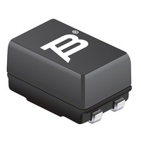
SRF0905-501Y Bourns Inc., SRF0905-501Y Datasheet

SRF0905-501Y
Manufacturer Part Number
SRF0905-501Y
Description
INDUCTOR COMMON MODE 500UH 1.0A
Manufacturer
Bourns Inc.
Series
SRF0905r
Datasheet
1.SRF0905-100Y.pdf
(2 pages)
Specifications of SRF0905-501Y
Impedance
1K Ohm
Package / Case
0.362" L x 0.236" W x 0.197" H (9.20mm x 6.00mm x 5.00mm)
Inductance
500µH
Current
1A
Dc Resistance (dcr)
150.0 mOhm Max
Filter Type
Common Mode - 2 Line Array
Mounting Type
Surface Mount
Product
Data Line EMI/RFI Filters
Tolerance
50 %
Maximum Dc Current
1 Amps
Maximum Dc Resistance
0.15 Ohms
Operating Temperature Range
- 40 C to + 105 C
Termination Style
SMD/SMT
Dc Current Max
1A
Dc Resistance Max
0.15ohm
Impedance Typ
1kohm
Inductance Min
500µH
Voltage Rating Vdc
50V
Filter Terminals
SMD
Filter Case
0905
No. Of Pins
4
Rohs Compliant
Yes
Lead Free Status / RoHS Status
Lead free / RoHS Compliant
Lead Free Status / RoHS Status
Lead free / RoHS Compliant, Lead free / RoHS Compliant
Other names
SRF0905-501Y
Available stocks
Company
Part Number
Manufacturer
Quantity
Price
Company:
Part Number:
SRF0905-501Y
Manufacturer:
BOURNS
Quantity:
410 000
Part Number:
SRF0905-501Y
Manufacturer:
BOURNS/伯恩斯
Quantity:
20 000
** Test condition: 10 - 50 μH, 0.1 V, 1 KHz; 250 - 6500 μH, 5 mV, 100 KHz
Model
Value Code (see table)
Tolerance Code (see table)
Part Number
SRF0905-100Y
SRF0905-250Y
SRF0905-400Y
SRF0905-500Y
SRF0905-251Y
SRF0905-471Y
SRF0905-501Y
SRF0905-102Y
SRF0905-202Y
SRF0905-472Y
SRF0905-652Y
Electrical Specifi cations @ 25 °C
Schematic
How to Order
2
1
= POLARITY
1000 ± 50 %
2000 ± 50 %
4700 ± 50 %
6500 ± 50 %
250 ± 50 %
470 ± 50 %
500 ± 50 %
10 ± 30 %
25 ± 30 %
40 ± 30 %
50 ± 30 %
N2
N1
(μH) **
SRF0905 - 102 Y
L
Leakage
Max.
(μH)
0.11
0.12
0.12
0.17
0.25
0.36
0.39
Ind.
16
18
22
8
3
4
(Ω) max.
winding)
(each
DCR
0.08
0.16
0.25
0.32
0.13
0.14
0.15
0.31
0.42
0.90
1.05
Features
■
■
■
■
SRF0905 Series - Line Filter
(.100)
Typical Part Marking
Recommended Layout
2.54
Current rating up to 1.6 A
Inductance range: 10 to 6500 μH
Frequency range to 300 MHz
RoHS compliant*
Voltage
Rated
(Vdc)
50
50
50
50
50
50
50
50
50
50
50
Current
100Y
Rated
(A)
1.6
1.0
0.9
0.8
1.2
1.1
1.0
0.8
0.6
0.4
0.3
(.374)
(.047)
9.5
1.2
20 - 300
20 - 150
20 - 100
20 - 100
Range
Impedance (Z)
(MHz)
0.3 - 3
0.3 - 2
3 - 20
2 - 20
1 - 20
1 - 15
Freq.
1 - 5
Customers should verify actual device performance in their specifi c applications.
Value
1500
1000
1000
1500
3000
4000
5000
Min.
200
600
800
600
(.047)
(Ω)
(.079)
1.2
2.0
*RoHS Directive 2002/95/EC Jan 27, 2003 including Annex.
Applications
■
Temperature Rise .. 45 °C at rated current
Hi-Pot .............................500 VAC, 60 Hz,
Operating Temperature
Storage Temperature .. -40 °C to +105 °C
Solderability .................260 °C for 5 sec.
Core Material ................................Ferrite
Base ................................................ LCP
Wire ........................... Enameled copper
Terminal coating .................................Sn
Packaging .....1000 pcs. per 13-inch reel
(.031 ± .008)
EMI suppression
0.8 ± 0.2
General Specifi cations
Materials
Product Dimensions
................................. -40 °C to +105 °C
Specifi cations are subject to change without notice.
2
1
(.100 ± .008)
2.54 ± 0.20
DIMENSIONS:
(Temperature rise included)
3 mA max. for 3 seconds
100Y
(.055)
(.224)
5.70
(.362 ± .012)
1.4
9.20 ± 0.30
(JEDEC J-STD-020D)
MAX.
REF.
(INCHES)
MM
(.039 ± .004)
1.00 ± 0.10
(.197 ± .012)
(.236 ± .012)
3
4
6.00 ± 0.30
5.00 ± 0.30
(.071)
MAX.
1.8
Related parts for SRF0905-501Y
SRF0905-501Y Summary of contents
Page 1
... SRF0905-250Y 25 ± SRF0905-400Y 40 ± SRF0905-500Y 50 ± SRF0905-251Y 250 ± 0.11 SRF0905-471Y 470 ± 0.12 SRF0905-501Y 500 ± 0.12 SRF0905-102Y 1000 ± 0.17 SRF0905-202Y 2000 ± 0.25 SRF0905-472Y 4700 ± 0.36 SRF0905-652Y 6500 ± 0.39 ** Test condition μH, 0 KHz; 250 - 6500 μH, 5 mV, 100 KHz ...
Page 2
... SRF0905 Series - Line Filter Impedance Graphs 7 5 500Y 400Y 3 250Y 1 100Y 0.7 0.5 0.3 0 100 300 Frequency (MHz) Packaging Specifi cations 330 2.0 ± 0.5 DIA. (12.99) (.079 ± .020) 21.0 ± 0.8 (.827 ± .031) 13.0 DIA. (.512) 12.0 ( ...


