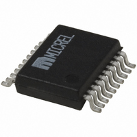
MIC2179YSM Micrel Inc, MIC2179YSM Datasheet

MIC2179YSM
Specifications of MIC2179YSM
Available stocks
Related parts for MIC2179YSM
MIC2179YSM Summary of contents
Page 1
General Description The Micrel MIC2179 is a 200kHz synchronous buck (step- down) switching regulator designed for high-efficiency, bat- tery-powered applications. The MIC2179 operates from a 4.5V to 16.5V input and features internal power MOSFETs that can supply up to 1.5A ...
Page 2
... Ordering Information Part Number Standard* Pb-Free MIC2179BSM MIC2179YSM MIC2179-3.3BSM MIC2179-3.3YSM MIC2179-5.0BSM MIC2179-5.0YSM * Standard product will be supported as Pb-Free IAW PCCN #040004 effective 1-1-2005 pending residual depletion. Pin Configuration Pin Description Pin Number Pin Name 1, 2, 19, 20 PGND 3 5 PWM 6 PWRGD 7 8 COMP 9– ...
Page 3
Absolute Maximum Ratings Supply Voltage [100ms transient] (V ................................................... Output Switch Voltage ( Output Switch Current (I ) ......................................... 6.0A SW Enable, PWM Control Voltage (V EN Sync Voltage (V ) ...................................................... 6V SYNC Electrical Characteristics V = ...
Page 4
Symbol Parameter Enable Threshold I Enable Leakage EN PWM Threshold I PWM Leakage PWM PWRGD Threshold PWRGD Output Low PWRGD Off Leakage Notes: 1. Exceeding the absolute maximum rating may damage the device. 2. The device is not guaranteed to ...
Page 5
Typical Characteristics Oscillator Frequency vs. Temperature 205 200 195 190 185 180 175 -60 - 120 150 TEMPERATURE (°C) Reference Voltage vs. Temperature 5.030 MIC2179-5.0 5.020 5.010 5.000 4.990 4.980 4.970 -60 - ...
Page 6
Block Diagram UVLO, Thermal Shutdown EN 3.3V Enable Regulator Shutdown 15 BIAS 14 R3 0.01µF 4.02k internal supply Voltage PWM PWM/ Skip Mode Skip-Mode PWM Mode 5 Select Corrective Ramp SYNC 200kHz Stop Oscillator 13 Reset Pulse R C COMP ...
Page 7
Functional Description Micrel’s MIC2179 is a synchronous buck regulator that oper- ates from an input voltage of 4.5V to 16.5V and provides a regulated output voltage of 1.25V to 16.5V. Its has internal power MOSFETs that supply up to 1.5A ...
Page 8
When V is lower than its nominal value, the error REF OUT amplifier output voltage increases. This voltage then intersects the current sense waveform later in switching period which increases the duty cycle and the average inductor current. ...
Page 9
PWM-Mode Functional Diagram Corrective Ramp 200kHz Stop Oscillator 13 Reset Pulse MIC2179 [Adjustable] PWM-Mode Signal Path Reset Pulse Error Amp. Output ...
Page 10
Skip-Mode Functional Diagram Output Control Logic MIC2179 [Adjustable] Skip-Mode Signal Path One-Shot Pulse 5mV – 5mV June 2009 One ...
Page 11
Application Information Feedback Resistor Selection (Adjustable Version) The output voltage is programmed by connecting an external resistive divider to the FB pin as shown in “MIC2179 Block Diagram.” The ratio determines the output voltage. To optimize ...
Page 12
The feedback resistors, RC compensation network, and BIAS pin bypass capacitor should be located close to their respective pins. To prevent ground bounce, their ground traces and SGND should not be in the path of switching Suggested Manufacturers List Inductors ...
Page 13
... Package Information MICREL INC. 2180 FORTUNE DRIVE SAN JOSE, CA 95131 USA + 1 (408) 944-0800 tel This information furnished by Micrel in this data sheet is believed to be accurate and reliable. However no responsibility is assumed by Micrel for its use. Micrel reserves the right to change circuitry and specifications at any time without notification to the customer. ...


