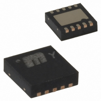
MIC2297-15YML TR Micrel Inc, MIC2297-15YML TR Datasheet - Page 10

MIC2297-15YML TR
Manufacturer Part Number
MIC2297-15YML TR
Description
IC,Laser Diode/LED Driver,LLCC,10PIN,PLASTIC
Manufacturer
Micrel Inc
Type
Backlight, White LEDr
Datasheet
1.MIC2297-42YML_TR.pdf
(11 pages)
Specifications of MIC2297-15YML TR
Topology
PWM, Step-Up (Boost)
Number Of Outputs
1
Internal Driver
Yes
Type - Primary
Backlight, Flash/Torch
Type - Secondary
White LED
Frequency
525kHz ~ 6.75kHz
Voltage - Supply
2.5 V ~ 10 V
Mounting Type
Surface Mount
Package / Case
10-MLF®, QFN
Operating Temperature
-40°C ~ 125°C
Current - Output / Channel
20mA
Internal Switch(s)
Yes
Lead Free Status / RoHS Status
Lead free / RoHS Compliant
Voltage - Output
-
Efficiency
-
Lead Free Status / RoHS Status
Lead free / RoHS Compliant
Other names
MIC2297-15YMLTR
MIC2297-15YMLTR
MIC2297-15YMLTR
Reference Capacitor
A 1uF ceramic should be used on the reference pin to
prevent noise from getting into this node. A 1uF ceramic is
needed when a PWM signal is connected to the BRT pin.
Diode Selection
The MIC2297 requires an external diode for operation. A
Schottky diode is recommended for most applications due
to their lower forward voltage drop and reverse recovery
time. Ensure the diode selected can deliver the peak
inductor current and the maximum reverse voltage is rated
greater than the output voltage.
Input capacitor
A minimum 1 F ceramic capacitor with an X5R or X7R
dielectric is recommended for designing with the MIC2297.
Increasing input capacitance will improve performance and
greater noise immunity on the source. The input capacitor
should be as close as possible to the inductor and the
MIC2297, with short traces for good noise performance.
The MIC2297 utilizes a feedback pin to compare the LED
current to an internal reference. The LED current is
adjusted by selecting the appropriate feedback resistor
value. The desired output current can be calculated as
follows:
Micrel
Mach 2008
I
LED
=
0
2 .
R
V
10
Compensation
The comp pin is connected to the output of the voltage
error
transconductance amplifier. Adding a series RC to ground
adds a zero at:
The resistor typically ranges from 10kOhm to 50kOhm.
The capacitor typically ranges from 1nF to 100nF.
Adding a capacitor from comp to ground adds a pole at
This capacitor typically ranges from 100pF to 10nF.
Generally an RC to ground is all that is needed. The RC
should be placed as close as possible to the comp pin.
The capacitor should be a ceramic with a X5R, X7R, or
COG dielectric.
Grounding
Both the AGND and PGND must be connected to the
exposed backside pad. The exposed backside pad also
improves thermal performance. A large ground plane
decreases thermal resistance to ambient air.
f
f
pole
zero
=
=
2
amplifier.
2
π
π
R
1
R
1
1
C
1
C
2
1
The
voltage
error
amplifier
M9999-032708
MIC2297
is
a


