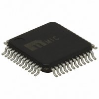
MIC2341R-2YTQ Micrel Inc, MIC2341R-2YTQ Datasheet - Page 25

MIC2341R-2YTQ
Manufacturer Part Number
MIC2341R-2YTQ
Description
Dual -Slot PCI Express Hot-Plug Controller
Manufacturer
Micrel Inc
Type
Hot-Swap Controllerr
Datasheet
1.MIC2341R-2YTQ.pdf
(32 pages)
Specifications of MIC2341R-2YTQ
Applications
General Purpose, PCI Express
Internal Switch(s)
No
Current Limit
Adjustable
Voltage - Supply
3.3V, 12V
Operating Temperature
0°C ~ 70°C
Mounting Type
Surface Mount
Package / Case
48-TQFP
Lead Free Status / RoHS Status
Lead free / RoHS Compliant
Other names
576-2987
Available stocks
Company
Part Number
Manufacturer
Quantity
Price
Hardware Interface
Once the input power supply voltages are above their
respective UVLO thresholds, the MIC2341/MIC2341R’s
hardware interface can be enabled for power control by
asserting
AUXEN[A/B], and ON[A/B]) appropriately for each slot.
The MIC2341/MIC2341R’s ON[A/B] and AUXEN[A/B]
signals are asserted active-HIGH, level-sensitive digital
inputs with internal pull-up 45kΩ resistors to VSTBY[A]
to save pc board area and external component costs. As
such, external hot-plug controllers connecting to these
pins should configure their respective output drivers to
OPEN-DRAIN and configure their firmware to de-assert
these signals to turn OFF either the MAIN[A/B] outputs
or the VAUX[A/B] outputs. As these input control signals
Micrel, Inc.
October 2007
where “1” = Logic HIGH
the
X
X
X
X
1
1
“0” = Logic LOW
“X” = Don’t care
control
X
X
X
X
X
1
X
X
X
0
0
0
input
X
X
X
1
1
1
pins
UV
X
X
X
X
X
(/CRSW[A/B],
Table 1. SYSPWRGD Truth Table
UV
X
X
X
X
X
UV
X
X
X
X
X
25
X
X
X
X
1
1
are already asserted after POR, the corresponding
/CRSW[A/B] control signal should be used to enable the
slot’s gate drive circuits to initiate a power-up sequence.
For example, in order for the MIC2341/MIC2341R to
switch on the VAUX supply for either slot, the
AUXEN[A/B] control can be enabled during or after the
power-on-reset operation (typically, t
timing response diagram of Figure 9 illustrates the
hardware interface operation where an overcurrent fault
is detected by the MIC2341/MIC2341R controller after
initiating a power-up sequence. The MAIN (+12V &
+3.3V) and VAUX[A/B] supply rails, /FAULT, /PWRGD
and /INT output responses for both AUX and MAIN are
shown in the figure.
X
X
X
X
X
1
X
X
X
0
0
0
X
X
X
1
1
1
UV
X
X
X
X
X
UV
X
X
X
X
X
UV
X
X
X
X
X
POR
MIC2341/2341R
M9999-102507-A
(408) 944-0800
= 160µs. The
0
0
0
0
0
0


