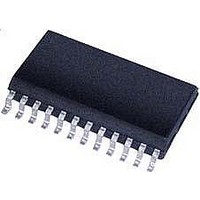
MTS62C19A-LS105 Microchip Technology, MTS62C19A-LS105 Datasheet - Page 6

MTS62C19A-LS105
Manufacturer Part Number
MTS62C19A-LS105
Description
Dual Full-Bridge PWM Motor Driver 24 SOIC .300in T/R
Manufacturer
Microchip Technology
Type
Dual Full Bridge PWM Motor Driverr
Datasheet
1.MTS62C19A-HS105.pdf
(18 pages)
Specifications of MTS62C19A-LS105
Applications
DC Motor Driver, Stepper Motor Driver
Number Of Outputs
1 or 2
Current - Output
750mA
Voltage - Load
10 V ~ 40 V
Voltage - Supply
4.5 V ~ 5.5 V
Operating Temperature
-20°C ~ 70°C
Mounting Type
Surface Mount
Package / Case
24-BFSOP (0.300", 7.50mm Width)
Product
Stepper Motor Controllers / Drivers
Operating Supply Voltage
10 V to 40 V
Supply Current
750 mA
Mounting Style
SMD/SMT
Lead Free Status / RoHS Status
Lead free / RoHS Compliant
Lead Free Status / RoHS Status
Lead free / RoHS Compliant
Available stocks
Company
Part Number
Manufacturer
Quantity
Price
Company:
Part Number:
MTS62C19A-LS105
Manufacturer:
MICROCHIP
Quantity:
12 000
MTS62C19A
2.0
The descriptions of the pins are listed in
TABLE 2-1:
2.1
Logic supply ground. Only the driver current flows out
of this pin; there is no high current. Minimize voltage
drops between this pin and the logic inputs.
2.2
Connect VLOGIC to the logic source voltage. Decouple
the supply with a 0.1 µF ceramic capacitor mounted
close to the VLOGIC and GND terminals.
2.3
Connect VLOAD to the motor positive voltage supply.
The motor current is supplied through this pin and the
selected output transistors.
DS22260A-page 6
SOP-24
Pin No.
10
11
12
13
14
15
16
17
18
19
20
21
22
23
24
1
2
3
4
5
6
7
8
9
PIN DESCRIPTIONS
Ground Terminal (GND)
Logic Supply Voltage (VLOGIC)
Load Supply Voltage (VLOAD)
MTS62C19A PIN FUNCTION TABLE
Output
Output
Output
Output
Power
Power
Power
Power
Power
Power
Type
Input
Input
Input
Input
Input
Input
Input
Input
Input
Input
Input
Input
Input
Input
COMPIN2
COMPIN1
SENSE2
PHASE2
PHASE1
SENSE1
VLOGIC
OUT1A
OUT2A
OUT2B
OUT1B
VLOAD
VREF2
VREF1
Name
GND
GND
GND
GND
RC2
RC1
I02
I12
I01
I11
Table
2-1.
Output 1 ‘A’ Side of Motor Winding
Output 2 ‘A’ Side of Motor Winding
Current Sense for Output 2
Current Sense Comparator Input for Output 2
Output 2 ‘B’ Side of Motor Winding
Negative Logic Supply (Ground)
Negative Logic Supply (Ground)
Output 2 Current Selection Bit 0
Output 2 Current Selection Bit 1
Output 2 Phase
Output 2 Current Reference
Output 2 RC Time Constant
Positive Logic Supply Voltage
Output 1 RC Time Constant
Output 1 Current Reference
Output 1 Phase
Output 1 Current Selection Bit 1
Negative Logic Supply (Ground)
Negative Logic Supply (Ground)
Output 1 Current Selection Bit 0
Output 1 ‘B’ Side of Motor Winding
Current Sense Comparator Input for Output 1
Current Sense for Output 1
Positive Load Supply Voltage
2.4
Comparator input for current threshold detection. The
voltage across the sense resistor is fed back to this
input through the low pass filter RcCc. The power tran-
sistors are disabled when the sense voltage exceeds
the reference voltage of the selected comparator.
When this occurs the current decays for a time set by
RtCt (T
OFF
Current Detection Selection
(I01, I02, I11, I12)
= 1.1 RtCt).
Function
2010 Microchip Technology Inc.


