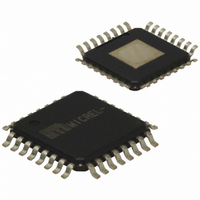
SY87813LHG Micrel Inc, SY87813LHG Datasheet - Page 7

SY87813LHG
Manufacturer Part Number
SY87813LHG
Description
3.3V Any-Rate 32-1250 Mbps CDR (I Temp, Green/32 Pin EP-TQFP/bulk)
Manufacturer
Micrel Inc
Type
Clock and Data Recovery (CDR)r
Datasheet
1.SY87813LHG_TR.pdf
(15 pages)
Specifications of SY87813LHG
Input
Differential
Output
Differential
Frequency - Max
1.3GHz
Voltage - Supply
3.15 V ~ 3.45 V
Operating Temperature
-40°C ~ 85°C
Mounting Type
Surface Mount
Package / Case
32-TQFP Exposed Pad, 32-eTQFP, 32-HTQFP, 32-VQFP
Frequency-max
1.3GHz
Lead Free Status / RoHS Status
Lead free / RoHS Compliant
Other names
576-1586
Functional Block
Functional Description
Clock Recovery
Clock recovery, as shown in the block diagram,
generates a clock that is at the same frequency as the
incoming data bit rate at the serial data input. The
clock is phase aligned by a PLL so that it samples the
data in the center of the data eye pattern.
The phase relationship between the edge transitions
of the data and those of the generated clock are
compared by a phase/frequency detector. Output
pulses from the detector indicate the required
direction of phase correction. These pulses are
smoothed by a filter. The output of the loop filter
controls the frequency of the Voltage Controlled
Oscillator (VCO), which generates the recovered
clock.
Frequency,
guaranteed by an alternate reference input (REFCLK
or REFCLKP/N) that the PLL locks onto when data is
lost. If the frequency of the incoming signal varies by
greater than approximately 900ppm with respect to
the synthesizer frequency, the PLL will be declared
out of lock, and the PLL will lock to the reference
clock.
November 2006
stability,
without
incoming
data,
is
7
The loop filter transfer function is optimized to enable
the PLL to track the jitter, yet tolerate the minimum
transition density expected in a received SONET data
signal.
Lock Detect
The SY87813L contains a link fault indication circuit,
which monitors the integrity of the serial data inputs. If
the recovered serial data from RDIN is at the correct
data
frequency), the Link Fault Indicator (LFIN) output will
then be asserted HIGH indicating an in-lock condition
and will remain HIGH as long as this condition is met.
In the event that the recovered serial data is not at the
correct data rate (greater than 900ppm difference
from the synthesizer frequency), then LFIN output will
go LOW indicating an out-of-lock condition. This
condition will force the Clock and Data Recovery PLL
(CDR) to lock onto the synthesizer frequency until it is
within the correct frequency range (less than 900ppm
difference from the synthesizer frequency). Once the
CDR is within the correct frequency range, it will again
lock onto the RDIN input.
rate
(within
hbwhelp@micrel.com
900ppm
of
the
or (408) 955-1690
M9999-112806-B
synthesizer


