SY88992LMG Micrel Inc, SY88992LMG Datasheet - Page 3
SY88992LMG
Manufacturer Part Number
SY88992LMG
Description
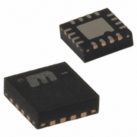
3.3V 4.25 Gbps VCSEL Driver With Peaking: 16 MLFr (I Temp, Green)
Manufacturer
Micrel Inc
Type
Laser Diode Driverr
Datasheet
1.SY88992LMG_TR.pdf
(11 pages)
Specifications of SY88992LMG
Data Rate
4.25Gbps
Number Of Channels
1
Voltage - Supply
3 V ~ 3.6 V
Current - Supply
57mA
Current - Modulation
25mA
Operating Temperature
-40°C ~ 85°C
Package / Case
16-MLF®, QFN
Mounting Type
Surface Mount
Lead Free Status / RoHS Status
Lead free / RoHS Compliant
Other names
576-2120-5
576-2120-5
576-2970-5
576-2120-5
576-2970-5


Micrel, Inc.
Pin Description
Truth Table
Peaking Current-to-Modulation Current Ratio Setting
January 2006
Notes:
1. I
2. Assuming a common anode VCSEL with its cathode tied to MOD+.
Pin Number
IP/I
IP_SET1
IP_SET2
IP_SET3
1, 4, 9, 12
MOD
MOD
5, 15
10
11
13
14
16
2
3
6
7
8
= 0 when MOD+ = H.
DIN+
H
X
L
0 %
NC
NC
NC
Pin Name
IPD_SET
IP_SET1
IP_SET2
IP_SET3
IM_SET
GND
5 %
MOD+
NC
NC
MOD-
DIN+
GND
VCC
DIN-
/EN
10 %
GND
NC
NC
Pin Function
Non-Inverting Input Data. Internally terminated with 50Ω to a reference voltage.
Inverting Input Data. Internally terminated with 50Ω to a reference voltage.
Peaking Current Setting. Connect this pin to GND and keep pins 7 and 8 open to set
peaking-to-modulation current ratio to 5%. Combinations of the three pins, as shown
in table below, will set different ratios up to 35%.
Peaking Current Setting. Connect this pin to GND and keep pins 6 and 8 open to set
peaking-to-modulation current ratio to 10%. Combinations of the three pins, as shown
in table below, will set different ratios up to 35%.
Peaking Current Setting. Connect this pin to GND and keep pins 6 and 7 open to set
peaking-to-modulation current ratio to 20%. Combinations of the three pins, as shown
in table below, will set different ratios up to 35%.
Inverted Modulation Current Output. Provides modulation current when input data is
negative.
Non-Inverted Modulation Current Output. Provides modulation current when input
data is positive.
Modulation Current Setting. The modulation current is set by applying a 0V to 1.2V
voltage at this pin.
Peaking Duration Setting. The peaking current duration is set by installing a resistor
between this pin and ground. The plot on page 6 shows peaking duration versus the
value of the resistor installed.
A low level signal applied to this pin will enable the output stage of the driver.
Internally pulled down to ground with 75kΩ resistor.
Ground. Ground and exposed pad must be connected to the plane of the most
negative potential.
Supply Voltage. Bypass with a 0.1µF//0.01µF low ESR capacitor as close to VCC pin
as possible.
DIN-
H
X
L
15 %
GND
GND
NC
20 %
GND
NC
NC
/EN
25 %
GND
GND
H
NC
L
L
3
30 %
GND
GND
NC
MOD+
35 %
GND
GND
GND
H
H
L
(1)
hbwhelp@micrel.com
MOD-
H
H
L
VCSEL Output
H
L
L
or (408) 955-1690
M9999-011306-A
SY88992L
(2)
Related parts for SY88992LMG
Image
Part Number
Description
Manufacturer
Datasheet
Request
R

Part Number:
Description:
Manufacturer:
Micrel Inc
Datasheet:
Part Number:
Description:
Manufacturer:
Micrel Inc
Datasheet:
Part Number:
Description:
Manufacturer:
Micrel Inc
Datasheet:
Part Number:
Description:
Manufacturer:
Micrel Inc
Datasheet:
Part Number:
Description:
Manufacturer:
Micrel Inc
Datasheet:
Part Number:
Description:
Manufacturer:
Micrel Inc
Datasheet:
Part Number:
Description:
Manufacturer:
Micrel Inc
Datasheet:
Part Number:
Description:
Manufacturer:
Micrel Inc
Datasheet:
Part Number:
Description:
Manufacturer:
Micrel Inc
Datasheet:
Part Number:
Description:
Manufacturer:
Micrel Inc
Datasheet:
Part Number:
Description:
Manufacturer:
Micrel Inc
Datasheet:
Part Number:
Description:
Manufacturer:
Micrel Inc
Datasheet:
Part Number:
Description:
Manufacturer:
Micrel Inc
Datasheet:
Part Number:
Description:
Manufacturer:
Micrel Inc
Datasheet: