ST1-DC12V PANASONIC EW, ST1-DC12V Datasheet - Page 3
ST1-DC12V
Manufacturer Part Number
ST1-DC12V
Description
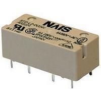
POWER RELAY SPST-NO/NC 12VDC 8A PC BOARD
Manufacturer
PANASONIC EW
Datasheet
1.ST1-DC12V.pdf
(5 pages)
Specifications of ST1-DC12V
Relay Type
PCB
Coil Voltage Vdc Nom
12V
Contact Current Max
8A
Contact Voltage Ac Nom
380V
Contact Voltage Dc Nom
250V
Coil Resistance
600ohm
Contact Configuration
SPST
Lead Free Status / RoHS Status
Lead free / RoHS Compliant
Available stocks
Company
Part Number
Manufacturer
Quantity
Price
Company:

Part Number:
ST1-DC12V
Manufacturer:
tyco
Quantity:
5 400
Company:
Part Number:
ST1-DC12V-F
Manufacturer:
ST
Quantity:
13 000
Part Number:
ST1-DC12V-F
Manufacturer:
PANASON
Quantity:
20 000


ST
2. Specifications
*1
*2
*3
*4
REFERENCE DATA
1. Max. switching power
3
Contact
Rating
Electrical
characteristics
Mechanical
characteristics
Expected life
Conditions
Unit weight
Characteristics
This value can change due to the switching frequency, environmental conditions, and desired reliability level, therefore it is recommended to check this with the actual
load.
Wave is standard shock voltage of 1.250s according to JEC-212-1981.
Refer to “6. Usage, Storage and Transport Conditions“ in
The max. operating speed amounts to 30cps without load.
0.5
0.2
0.1
10
5
2
1
DC resistive load
10
20
Arrangement
Contact material
Initial contact resistance, max.
Max. switching power (resistive load)
Max. switching voltage
Max. switching current
Minimum operating power
Nominal operating power
Min. switching capacity (Reference value)
Insulation resistance (Initial)
(at 25C, 50% relative humidity)
Breakdown voltage
(Initial)
Surge breakdown voltage (Initial)
Operate time [Set time] (at 20C 68F)
Release time [Reset time] (at 20C 68F)
Temperature rise (at 60C 140F)
Shock resistance
Vibration resistance
Mechanical
Electrical
Conditions for operation, transport and storage
Max. operating speed
inductive load
AC
(cosϕ =0.4)
50
Voltage, V
100 200 300
AC resistive load
Between open contacts
Between contact sets
Between contact and coil
Functional
Destructive
Functional
Destructive
Item
*2
2. Coil temperature rise
AMBIENT ENVIRONMENT section in Relay Technical
*1
100
90
80
70
60
50
40
30
20
10
0
*3
Contact current 8A
0.2
1 Form A 1 Form B, 2 Form A
Au-flashed AgSnO
Max. 30 m (By voltage drop 6 V DC 1A)
3,040 VA, 150 W
380 V AC, 250 V DC
8 A
150mW (Single side stable, 2 coil latching)
240mW (Single side stable, 2 coil latching)
100 mA 5V DC
Min. 1,000M (at 500V DC)
Measurement at same location as “Initial breakdown voltage” section.
1,200 Vrms for 1 min. (Detection current: 10 mA)
2,000 Vrms for 1 min. (Detection current: 10 mA)
3,750 Vrms for 1 min. (Detection current: 10 mA)
6,000 V (Between contact and coil)
Max. 15 ms [Max. 15 ms]
(Nominal voltage applied to the coil, excluding contact bounce time.)
Max. 10 ms [Max. 15 ms]
(Nominal voltage applied to the coil, excluding contact bounce time.) (without diode)
Max. 55C
(By resistive method, nominal voltage applied to the coil; contact carrying current: 8A.)
Min. 196 m/s
Min. 980 m/s
10 to 55 Hz at double amplitude of 2 mm (Detection time: 10s.)
10 to 55 Hz at double amplitude of 3 mm
Min. 10
Min. 10
Ambient temperature: –40C to +60C
Humidity: 5 to 85% R.H. (Not freezing and condensing at low temperature)
20 cpm
Approx. 10g
0.4
Coil operating power, W
7
5
*4
(8 A 250 V AC resistive) (ON : OFF = 1 s : 5 s)
(at 180 cpm)
0.6
2
2
.353 oz
(Half-wave pulse of sine wave: 11 ms; detection time: 10s.)
(Half-wave pulse of sine wave: 6 ms.)
0.8
0A
2
type
1.0
1.2
Specifications
–40F to
Information.
3. Influence of adjacent mounting
-10
-20
-30
-40
+140F;
40
30
20
10
0
ds_61A09_en_st: 250210D
5
Inter-relay distance, mm
Drop-out voltage
Pick-up voltage
10
15
20
Related parts for ST1-DC12V
Image
Part Number
Description
Manufacturer
Datasheet
Request
R


Part Number:
Description:
RELAY, SPNO/SPNC, 12V
Manufacturer:
PANASONIC EW
Datasheet:
Part Number:
Description:
ST Relay (2 Coil Latch, AgSnO2)
Manufacturer:
PANASONIC EW
Datasheet:

Part Number:
Description:
SWITCH
Manufacturer:
APEM Components
Datasheet:
Part Number:
Description:
ST Relay (Cd-Free)
Manufacturer:
PANASONIC EW
Datasheet:

Part Number:
Description:
SIGNAL RELAY, DPDT, 5VDC, 2A, PC BOARD
Manufacturer:
PANASONIC EW
Datasheet:


Part Number:
Description:
PHOTOMOS RELAY, 60VDC, 400mA
Manufacturer:
PANASONIC EW
Datasheet:

Part Number:
Description:
PHOTOMOS RELAY, 400V, 150mA
Manufacturer:
PANASONIC EW
Datasheet: