SCDQ5541Q OSRAM Opto Semiconductors Inc, SCDQ5541Q Datasheet
SCDQ5541Q
Specifications of SCDQ5541Q


Related parts for SCDQ5541Q


SCDQ5541Q Summary of contents
Page 1
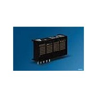
... Square 0.134" 4-Character 5x5 Dot Matrix Serial Input Dot Addressable Intelligent Display® Devices Lead (Pb) Free Product - RoHS Compliant SCDQ554xQ Yellow Super-red Green High Efficiency Green SCDQ5544P/Q/R DESCRIPTION The SCDQ5541X (Yellow), SCDQ5542X (Super-red), SCDQ5543X (Green), and SCDQ5544X (High Efficiency Green) are four digit, dot addressable dot matrix, serial input, alphanumeric Intelligent Display devices in a square format ...
Page 2
... SCDQ5541P/Q/R, SCDQ5542P/Q/R, SCDQ5543P/Q/R, SCDQ5544P/Q/R Ordering Information Type Color of Emission SCDQ5541P yellow SCDQ5542P super-red SCDQ5543P green SCDQ5544P high efficiency green SCDQ5541Q yellow SCDQ5542Q super-red SCDQ5543Q green SCDQ5544Q high efficiency green SCDQ5541R yellow SCDQ5542R super-red SCDQ5543R green SCDQ5544R high efficiency green 2006-05-12 Character Height ...
Page 3
... Description Luminous Intensity Character Average (#displayed all digits) (typ.) Peak Wavelength Dominant Wavelength Notes: 1. Dot to dot intensity matching at 100% brightness is 1.8:1. 2. Displays are binned for hue at 2.0 nm intervals. 3. Displays within a given intensity category have an intensity matching of 1.5:1 (max.). 2006-05-12 Symbol stg V ...
Page 4
... Part marking is on this side of the display. RoHS Compliant (lead-free) have a "Z" marked to the right of the date code. 2) Molex header, 53290-0510 mounted on the display. 3) Molex receptacle, 52418-0510 mounted on the customer’s PCB. Supplied by the customer. ...
Page 5
... V — 10 µA — –10 µA 768 1086 Hz 65 — °C IDCD5021 5 = 25°C) A Conditions — V =5.0 V, all inputs =5.0 V, “#” displayed in all 4 digits CC at 100% brightness at 25× 5.0 V (all inputs) CC IN (all inputs — — ...
Page 6
... Time Between Writes BL T Reset Active Time RST Notes =Setup Time + 8 Clock Times + Hold Times + Time Between Writes Data is shifted into the display’s 8 bit shift register on the positive going edge of the SDCLK. 3. Shift register data is evaluated when Load goes high. 2006-05- ...
Page 7
... Pins/Conector located at the top of the display Char 0 1. Viewed from the LED side of the display with the display in a IDOD5012 horizontal position. 2. The row address and column data are typical for all character posi- tions. The LED is on when the data bit = 1 and off when the data bit = 0 ...
Page 8
... SDATA LOAD The following explains how to format the serial data to be loaded into the display. The user supplies a string of bit mapped decoded char- acters. The contents of this string is shown in Figure „Loading Serial Character Data A“ (page 8). Figure „Loading Serial Character Data B“ (page 8) shows that each character consists of six 8 bit words. The first word encodes the display character location and the suc- ceeding five bytes are row data. The row data represents the status (On, Off) of individual column LEDs. Figure „ ...
Page 9
... Figure „Writing Character ’D’ Example“ (page 9) shows the Row Address for the example character “D” See Figure „Character Address, Row, & Column Data Map“ (page 7) for the dot positioning (Display contacts are at the top of the display). Instruction Set OPERATION ...
Page 10
... FF 0% (>10 cm). brightness Good digital grounds (pin 1) and power supply decoupling (pin 2) will insure that I erate localized ground bounce. Therefore it is recommended that each display package use a 0.1 µF and 20 µF capacitor between V and ground Load Row 3 Load Row 4 Row 0 Row 0 ...
Page 11
... The circular polarizing further enhances contrast by reducing the light that travels through the fil- ter and reflects back off the display to less than 1%. Several filter manufacturers supply quality filter materials. Some of them are: Panelgraphic Corporation, W. Caldwell, NJ; SGL Homa- lite, Wilmington, DE ...
Page 12
... Upon power up display will come on at random. Thus the display should be reset at power-up. The reset will set the Address Register to Digit 0, User RAM is set to 0 (display blank) the Control Word is set to 0 (100% brightness with Lamp Test off) and the internal counters are reset ...
Page 13
... Step B: Load the Control Word with the desired brightness level. 4. Load the Digit Address into the display. 5. Load display row and column data for the selected digit. 6. Repeat steps 4 and 5 for all digits. Data Contents for the Display in a Horizontal Format “ ...
Page 14
SCDQ5541P/Q/R, SCDQ5542P/Q/R, SCDQ5543P/Q/R, SCDQ5544P/Q/R User Definable Character Set Examples* Upper and lower case alphabets HEX HEX CODE CODE ...
Page 15
SCDQ5541P/Q/R, SCDQ5542P/Q/R, SCDQ5543P/Q/R, SCDQ5544P/Q/R User Definable Character Set Examples* (continued) Scientific notations, ect. HEX HEX CODE CODE ...
Page 16
SCDQ5541P/Q/R, SCDQ5542P/Q/R, SCDQ5543P/Q/R, SCDQ5544P/Q/R Revision History: 2006-05-12 Previous Version: 2006-01-23 Page Subjects (major changes since last revision) all Lead free device ublished by P OSRAM Opto Semiconductors GmbH Wernerwerkstrasse 2, D-93049 Regensburg www.osram-os.com © All Rights Reserved. Attention please! The ...