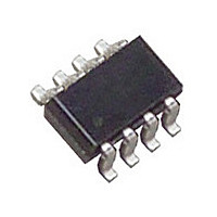
LTC2927CTS8#PBF Linear Technology, LTC2927CTS8#PBF Datasheet - Page 14

LTC2927CTS8#PBF
Manufacturer Part Number
LTC2927CTS8#PBF
Description
Manufacturer
Linear Technology
Datasheet
1.LTC2927CTS8PBF.pdf
(16 pages)
Specifications of LTC2927CTS8#PBF
Operating Temperature (max)
70C
Operating Temperature (min)
0C
Pin Count
8
Mounting
Surface Mount
Package Type
TSOT-23
Case Length
2.9mm
Screening Level
Commercial
Lead Free Status / RoHS Status
Compliant
Available stocks
Company
Part Number
Manufacturer
Quantity
Price
APPLICATIO S I FOR ATIO
LTC2927
Start-Up Delays
Often power supplies do not start-up immediately when
their input supplies are applied. If the LTC2927 tries to
ramp-up these power supplies as soon as the input sup-
ply is present, the start-up of the outputs may be delayed,
defeating the tracking circuit (Figure 18). Often this delay is
intentionally confi gured by a soft-start capacitor. This can
be remedied either by reducing the soft-start capacitor on
the slave supply or by including a capacitor in the ON pin’s
resistive divider to delay the ramp up. See Figure 19.
14
1V/DIV
1V/DIV
Figure 18. Power Supply Start-Up Delayed
Figure 19. ON Pin Delayed
U
20ms/DIV
U
5ms/DIV
W
2927 F18
2927 F19
U
MASTER
SLAVE
ON
MASTER
SLAVE
ON
Layout Considerations
Be sure to place a 0.1μF bypass capacitor as near as pos-
sible to the supply pin of the LTC2927.
To minimize the noise on the slave supply’s output, keep
the trace connecting the FB pin of the LTC2927 and the
feedback node of the slave supply as short as possible.
In addition, do not route this trace next to signals with
fast transition times. In some circumstances it might be
advantageous to add a resistor near the feedback node of
the slave supply in series with the FB pin of the LTC2927.
This resistor must not exceed:
This resistor is most effective if there is already a ca-
pacitor at the feedback node of the slave supply (often a
compensation component). Increasing the capacitance on
a slave supply’s feedback node will further improve the
noise immunity, but could affect the stability and transient
response of the supply.
R
SERIES
=
1 5
LTC2927
Figure 20. Layout Considerations
0.1μF
.
I
V V
MAX
−
GND
V
FB
CC
FB
2927 F20
=
⎛
⎜
⎝
1 5
V
MINIMIZE
.
LENGTH
FB
TRACE
V
−
R
1
SERIES
⎞
⎟
⎠
(
R
FA
R
R
FA
FB
FB
DC/DC
R
)
FB
OUT
2927fb


