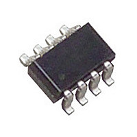
LTC2909ITS8-3.3#PBF Linear Technology, LTC2909ITS8-3.3#PBF Datasheet - Page 13

LTC2909ITS8-3.3#PBF
Manufacturer Part Number
LTC2909ITS8-3.3#PBF
Description
Manufacturer
Linear Technology
Datasheet
1.LTC2909ITS8-3.3PBF.pdf
(16 pages)
Specifications of LTC2909ITS8-3.3#PBF
Voltage Supervisor Type
Voltage Monitor
Number Of Voltage Supervisors
3
Monitored Supervisor Voltage
3.3
Operating Supply Voltage (min)
0.5V
Operating Supply Voltage (max)
6V
Package Type
TSOT-23
Operating Temperature Classification
Industrial
Operating Temp Range
-40C to 85C
Pin Count
8
Mounting
Surface Mount
Lead Free Status / RoHS Status
Compliant
Available stocks
Company
Part Number
Manufacturer
Quantity
Price
Part Number:
LTC2909ITS8-3.3#PBFLTC2909ITS8-3.3#TRPBF
Manufacturer:
LINEAR
Quantity:
10 000
APPLICATIO S I FOR ATIO
APPLICATIO S I FOR ATIO
If the user wishes to avoid having an external capacitor,
the TMR pin should be tied to ground, switching the part
to an internal 200ms timer.
If the user requires a shorter timeout than 400μs, or
wishes to perform application-specifi c processing of the
reset output, the part may be put in comparator mode by
tying the TMR pin to V
is bypassed and comparator outputs go straight to the
reset output.
The current required to hold TMR at ground or V
about 2μA. To force the pin from the fl oating state to
ground or V
transition.
When the part is in comparator mode, one of the two
means of preventing false reset has been removed, so
a small amount of one-sided hysteresis is added to the
inputs to prevent oscillation as the monitored voltage
passes through the threshold. This hysteresis is such
that the valid-to-invalid transition threshold is unchanged,
but the invalid-to-valid threshold is moved by about
0.7%. Thus, when the ADJ input polarity is positive,
the threshold voltage is 500mV nominal when the in-
put is above 500mV. As soon as the input drops below
500mV, the threshold moves up to 503.5mV nominal.
Conversely, when confi gured as a negative-polarity input,
Table 3. Suggested Resistor Values for 5% Monitoring
Trip points are nominal voltage ±6.5%.
NOMINAL
VOLTAGE
–12
–15
3.3
2.5
1.8
1.5
1.2
24
15
12
–5
–9
9
5
1
CC
may require as much as 100μA during the
U
U
49.9k
63.4k
59.0k
97.6k
232k
115k
115k
137k
221k
115k
127k
200k
133k
107k
107k
R
X1
CC
. In comparator mode, the timer
U
U
5% UV
10.2M
3.09M
1.07M
1.82M
1.15M
1.15M
1.37M
1.74M
2.49M
3.09M
422k
150k
107k
158k
174k
W
W
R
X2
U
U
78.7k
51.1k
40.2k
102k
200k
102k
137k
340k
115k
137k
102k
100k
118k
115k
309k
R
X1
CC
is
5% OV
the threshold is 500mV when the input is below 500mV,
and switches to 496.5mV when the input goes above
500mV.
The comparator mode feature should be enabled by directly
shorting the TMR pin to the V
any other voltage may have unpredictable results.
Selecting the Reset Timing Capacitor
Connecting a capacitor, C
ground sets the reset timeout, t
approximates the value of capacitor needed for a particular
timeout:
Leaving the TMR pin open with no external capacitor
generates a reset timeout of approximately 400μs.
Maximum length of the reset timeout is limited by the
ability of the part to charge a large capacitor on start-up.
Initially, with a large (discharged) capacitor on the TMR
pin, the part will assume it is in internal timer mode (since
the pin voltage will be at ground). If the 2μA fl owing out of
the TMR pin does not charge the capacitor to the ground-
sense threshold within the fi rst 200ms after supplies
become good, the internal timer cycle will complete and
⎯ R ⎯ S ⎯ T will go high too soon.
C
5.11M
6.19M
2.49M
1.43M
1.33M
2.05M
1.37M
2.32M
1.07M
10.2M
221k
324k
301k
158k
113k
R
TMR
X2
= t
⎯ R ⎯ S ⎯ T
• 110 [pF/ms]
82.5k
76.8k
76.8k
76.8k
76.8k
82.5k
76.8k
40.2k
162k
137k
187k
107k
174k
182k
309k
R
X4
TMR
CC
5% UV and OV
, between the TMR pin and
RST
pin. Connecting the pin to
11.5k
10.7k
10.7k
22.6k
10.7k
10.7k
19.1k
11.5k
10.7k
26.1k
15.0k
20.0k
22.6k
5.11k
40.2k
R
. The following formula
X5
LTC2909
4.12M
2.37M
1.87M
2.94M
2.00M
3.65M
1.07M
10.2M
732k
453k
576k
221k
158k
267k
105k
R
X6
13
2909fb


