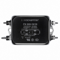
FN660-16-10 Schaffner EMC Inc, FN660-16-10 Datasheet - Page 6

FN660-16-10
Manufacturer Part Number
FN660-16-10
Description
FILTER 2-STAGE GENERAL 16A
Manufacturer
Schaffner EMC Inc
Series
FN 660r
Specifications of FN660-16-10
Filter Type
Power Line
Voltage - Rated
250V
Current
16A
Inductance
440µH
Mounting Type
Chassis Mount
Termination Style
Stud Lug
Current Rating
16A
Voltage Rating
250V
Leakage Current Max
190µA
Capacitance
0.15µF
Inductance Min
440µH
Termination Type
Screw
Mounting Style
Chassis
Filtered
Yes
Frequency
DC to 400 Hz
Leakage Current
190 uA
Product
Power Line Filters
Filter Terminals
Screw
Rohs Compliant
Yes
Lead Free Status / RoHS Status
Lead free / RoHS Compliant
Lead Free Status / RoHS Status
Lead free / RoHS Compliant, Lead free / RoHS Compliant
Other names
282-355
817-1222
FN 660 -16 /10
817-1222
FN 660 -16 /10
Available stocks
Company
Part Number
Manufacturer
Quantity
Price
Company:
Part Number:
FN660-16-10
Manufacturer:
SCHAFFNE
Quantity:
25
79
56
66
46
66
Figure 1. Permissible interference limits
for EN 50081-1
Figure 2. EN 50081-2 limits
Interference sources and
spectrums
The most common source of conducted
EMI is power electronic products such as
switched mode power supplies (SMPS),
pulse width modulated (PWM) frequency
converters or motor drives, and phase
angle controllers.
The emissions spectrum typically starts off
very large at low frequency and rolls off as
frequency increases. The point at which
the noise falls below the permitted limits
depends on several factors, the most
important being the frequency of
operation and the rise time of the
semiconductor devices.
Interference spectrums generated can be
either continuous, as in the case of phase
angle controllers, (Figure 3) or discrete
which is typical of the SMPS (Figure 4).
Figure 3. Continuous spectrum
0.15
0.15
Level
Level
Pegel
(dB)
dB
dB
Level
(dB V)
Level
(dB V)
LIGHT INDUSTRIAL & DOMESTIC
0.5
0.5
56
46
INDUSTRIAL
73
60
Quasi-peak
Average
Frequency Hz
Frequency (Hz)
Frequenz Hz
Frequency (MHz)
60
5
5
50
Frequency (MHz)
Quasi-peak
Average
30
30
Figure 4. Discrete spectrum
Interference propagation
EMI can propagate by two means:
• by radiation - where the energy can be
coupled either through magnetic or
electric field, or as an electro-magnetic
wave between the source and the victim
• by conduction - where the EMI energy
will propagate along power supply lines
and data cables
Radiated and conducted EMI cannot be
thought of as totally separate problems,
because noise conducted along a cable
may be radiated as the cable acts as an
antenna. The radiation will increase as the
cable length becomes comparable to the
wavelength of the noise. Also, the cable
will act as a receiving antenna and pick up
radiated interference.
Below around 150MHz, the most efficient
radiating devices in a system are usually
the power supply and data cables. Proper
filtering of these cables will reduce
radiation due to the cables as well as
conducted interference.
Above around 150MHz, PCB tracks and
short internal cables will start to become
efficient antennas. To reduce this radiation
a PCB should be laid out to reduce track
length and loop areas; ground planes
should be used if possible. Decoupling of
digital ICs is very important and shielding
may be necessary.
Interference types
To understand the problems associated
with conducted EMI it is first necessary to
understand the two modes of conducted
noise: differential mode (or symmetrical
mode) and common mode (or
asymmetrical mode). Differential mode
interference creates a voltage between the
phases of the system and is independent
of earth; the differential mode currents
Level
Level
(dB)
dB
Frequency Hz
Frequency (Hz)
flow along one phase and returns along
another phase (Figure 5).
Common mode noise creates a voltage
between each phase and the earth. The
common mode currents flow from the
noise source to the earth (usually via a
parasitic capacitance) along the earth path
and returns along the phases. (See Figure
6) A power line filter must be designed to
attenuate both common mode and
differential mode interference.
Figure 5. Differential mode interference
(V
Figure 6. Common mode interference
(V
Mains filters
Maximum power transfer occurs when
source and load impedances are matched.
A power line filter is an inductor-capacitor
network that aims to cause maximum
mismatch between impedances, and
therefore reduces the amount of EMI
power to be transferred from the noise
source onto the power line cable. Figure 7
shows a typical single-phase power line
filter.
Figure 7. A typical single-phase power
line filter
DM
CM
Neutral
Neutral
Line
Earth
Line
Earth
)
)
V
Line
Neutral
Live
Earth
DM
V
CM
R Cx
V
CM
L
L
1
2
Cx
Cy
5


