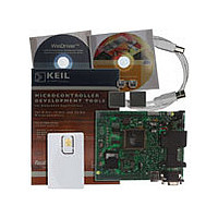
AT89STK03 Atmel, AT89STK03 Datasheet - Page 11

AT89STK03
Manufacturer Part Number
AT89STK03
Description
Manufacturer
Atmel
Datasheet
1.AT89STK03.pdf
(38 pages)
Specifications of AT89STK03
Lead Free Status / RoHS Status
Supplier Unconfirmed
7609B–SCR–11/06
Hardware Description
2.4.2
2.4.3
2.4.4
2.4.5
2.4.6
2-8
USB Peripheral
SPI
RS232
SIM Alternate Card
PLL Filter
All the required hardware to develop a USB firmware is available and includes:
An SPI interface is available.
All the required hardware to manage a RS232C interface is available. Tx and Rx can be
connected to the LEDs (Rx and Tx) by means of SW28 and SW29 solder pads on solder
side of the board.
The following hardware is supplied:
1. PLCC68 / VQFP64
PLL Filter is composed by C7, C10, R9
2. PLCC28
PLL filter is composed by C25, R16, C26.
Name
LED2
LED3
LED4
LED5
LED6
TX
RX
– a USB connector
– 2 test points D+ / D-
– a DETACH pushbutton which enables to connect / disconnect the pull-up on D+ and then to
– 9 pin SUBD connector
– Transceiver MAX202
– SIM connector
– power supply jumper
simulate an USB Attach/Detach operation. This avoids removals and insertions of the USB
cable.
5V power supply
5V
Color
Green
Green
Green
Green
Green
Green
Red
3.3V
Description
General purpose led - Connected to P3.6 - Enabled by LED2 jumper or SW21
solder pad
General purpose led - Connected to P3.7 - Enabled by LED3 jumper or SW22
solder pad
General purpose led - Connected to P4.3 (Only on PLCC68 / VQFP64 packages)
- Enabled by LED4 jumper
General purpose led - Connected to P4.4 (Only on PLCC68 / VQFP64 packages)
- Enabled by LED5 jumper
General purpose led - Connected to P4.5 (Only on PLCC68 / VQFP64 packages)
- Enabled by LED6 jumper or SW25 solder pad
Serial Transmission Line Status - Connected to TXD / P3.1 - Enabled by SW28
solder pad
Serial Reception Line Status - Connected to RXD / P3.0 - Enabled by SW29
solder pad
SIM PWR
3.3V power supply
5V
3.3V
AT89STK-03 Hardware User Guide


