ISD2310 OSRAM Opto Semiconductors Inc, ISD2310 Datasheet - Page 16
ISD2310
Manufacturer Part Number
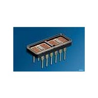
ISD2310
Description
LED Displays 5x7 Hyper Red 0.2 , 4-CHARACTER
Manufacturer
OSRAM Opto Semiconductors Inc
Datasheet
1.ISD2010.pdf
(16 pages)
Specifications of ISD2310
Display Type
Dot Matrix
Emitting Color
Red
Number Of Digits
4
Digit Size (in)
2in
Viewing Area Height (mm)
5.08mm
Viewing Area Length (mm)
2.84mm
Package Type
Panel
Operating Supply Voltage (min)
4.75V
Operating Supply Voltage (typ)
5V
Operating Supply Voltage (max)
5.25V
Operating Temperature Classification
Industrial
Operating Temp Range
-55C to 100C
Mounting
Through Hole
Pin Count
12
Total Thickness (mm)
2.54mm
Opto Display Type
Panel
Pattern Type
Dot Matrix
Millicandela Rating
370µcd
Size / Dimension
0.79" L x 0.33" W x 0.10" H (20.07mm x 8.43mm x 2.54mm)
Color
Red
Configuration
5 x 7
Character Size
2 in
Illumination Color
Red
Wavelength
660 nm
Maximum Operating Temperature
+ 100 C
Minimum Operating Temperature
- 55 C
Luminous Intensity
370 ucd
Viewing Area (w X H)
2.84 mm x 5.08 mm
Lead Free Status / RoHS Status
Compliant
Voltage - Forward (vf) Typ
-
Internal Connection
-
Lead Free Status / Rohs Status
Details
Other names
Q68000A8138


Remarks:
1)
2)
3)
4)
5)
6)
7)
8)
9)
10)
11)
12)
Published by
OSRAM Opto Semiconductors GmbH
Wernerwerkstrasse 2, D-93049 Regensburg
www.osram-os.com
© All Rights Reserved.
2006-04-04
Operation above +100°C ambient is possible if the following conditions are met.
The junction should not exceed T
should not exceed TC=100°C.
Maximum allowable dissipation is derived from:
V
Dimensions are specified as follows: inch (mm)
V
All typical values specified at V
The displays are categorized for luminous intensity with the intensity category designated by a letter code on the
bottom of the package.
The luminous sterance of the LED may be calculated using the following relationships:
L
L
A=5.3 x 10
Dominant wavelength (l
which defines the color of the device.
All typical values specified at V
The luminous intensity is measured at T
measurement.
A critical component is a component used in a life-support device or system whose failure can reasonably be
expected to cause the failure of that life-support device or system, or to affect its safety or the effectiveness of that
device or system.
Life support devices or systems are intended
(a) to be implanted in the human body,
or
(b) to support and/or maintain and sustain human life.
If they fail, it is reasonable to assume that the health or the life of the user may be endangered.
V
V
CC
B
(cd/m
(Footlamberts) = p l
Pulse Width Frequency—50 kHz (max.)
=5.25 V, V
2
) = l
–8
V
m
B
(Candela)/A (Meter)
=2.4 V, V
2
= 5.8 x 10
v
(Candela)/A (Foot)
dom
COL
–7
) is derived from the CIE chromaticity diagram and represents the single wavelength
=3.5 V 20 LEDs on per character, 20% DF.
(Foot)
CC
CC
J
=5.0 V and T
=5.0 V and T
=125°C and the case temperature (as measured at pin 1 or the back of the display)
2
2
2
A
=T
A
A
=25°C unless otherwise noted.
=25°C unless otherwise noted.
J
=25°C. No time is allowed for the device to warm up prior to
16
ISD201X, ISD231X, ISD235X
Related parts for ISD2310
Image
Part Number
Description
Manufacturer
Datasheet
Request
R

Part Number:
Description:
INTELLIGENT DISP 4CHAR 5X7 HERED
Manufacturer:
OSRAM Opto Semiconductors Inc
Datasheet:

Part Number:
Description:
DISPLAY 8DIGIT CERAMIC GREEN
Manufacturer:
OSRAM Opto Semiconductors Inc
Datasheet:

Part Number:
Description:
EMITTER IR 950NM 5MM SMD RADIAL
Manufacturer:
OSRAM Opto Semiconductors Inc
Datasheet:

Part Number:
Description:
LED TOPLED GREEN 570NM 2-PLCC
Manufacturer:
OSRAM Opto Semiconductors Inc
Datasheet:

Part Number:
Description:
INTERRUPTER RELFECT W/FILTR SMD
Manufacturer:
OSRAM Opto Semiconductors Inc
Datasheet:

Part Number:
Description:
LED Displays 5x7 Green 0.145 , 4-CHARACTER
Manufacturer:
OSRAM Opto Semiconductors Inc
Datasheet:

Part Number:
Description:
Q65110A4321_SIDELED PURE GREEN EOL150407
Manufacturer:
OSRAM Opto Semiconductors Inc
Datasheet:
Part Number:
Description:
Q65110A1202_RO DETECTOR 3/5MM_TR_RO
Manufacturer:
OSRAM Opto Semiconductors Inc
Datasheet:

Part Number:
Description:
PHOTODIODE 900NM 3MM W/FILTER
Manufacturer:
OSRAM Opto Semiconductors Inc
Datasheet:
Part Number:
Description:
INTELLIGENT DISP 4CHAR 5X7 HERED
Manufacturer:
OSRAM Opto Semiconductors Inc
Datasheet:
Part Number:
Description:
LED TOPLED GREEN 570NM 2-PLCC
Manufacturer:
OSRAM Opto Semiconductors Inc
Datasheet:
Part Number:
Description:
PHOTODIODE 900NM 3MM W/FILTER
Manufacturer:
OSRAM Opto Semiconductors Inc
Datasheet:

Part Number:
Description:
PHOTODIODE 850NM THRU-HOLE
Manufacturer:
OSRAM Opto Semiconductors Inc
Datasheet:

Part Number:
Description:
PHOTODIODE 880NM W/FILTER SMD
Manufacturer:
OSRAM Opto Semiconductors Inc
Datasheet: