E2EM-X4C1-M1 Omron, E2EM-X4C1-M1 Datasheet - Page 2
E2EM-X4C1-M1
Manufacturer Part Number
E2EM-X4C1-M1
Description
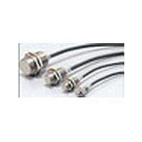
Proximity Sensors M8 NPN Out 2mm 3WIRE Xtnded rng inductive
Manufacturer
Omron
Series
E2EMr
Type
Inductive Proximity Sensorr
Specifications of E2EM-X4C1-M1
Proximity Sensor Sensing Distance
4mm
Proximity Sensor Sensing Distance Range
2 to 7mm
Proximity Sensor Switching Mode
NO
Mounting
Panel
Operating Temp Range
-40C to 85C
Operating Temperature Classification
Industrial
Operating Supply Voltage (min)
10V
Operating Supply Voltage (typ)
12/15/18/24V
Operating Supply Voltage (max)
40V
Pin Count
4
Output Type
NPN
Maximum Operating Temperature
+ 85 C
Supply Voltage
30 V
Operating Supply Voltage
10 V to 40 V
Sensing Distance
4 mm
Minimum Operating Temperature
- 25 C
Features
High visibility indicator
Sensor Type
Inductive
Sensing Object
Metallic
Response Frequency
500Hz
Material - Body
Brass
Shielding
Shielded
Voltage - Supply
10 V ~ 40 V
Terminal Type
Connector
Package / Case
Cylinder, Threaded - M12
Lead Free Status / RoHS Status
Compliant


Accessories (Order Separately)
Sensor I/O Connectors (M12)
Note: Refer to Introduction to Sensor I/O Connectors for details.
Ratings and Specifications
E2EM-X@X@ DC 2-Wire Models
*1. Use the Sensor within the range in which the setting indicator (green LED) is ON (except X2 Models).
*2. The response frequency is an average value.
*3. The residual voltage is 5 V. Make sure that the device connected to the Sensor can withstand the residual voltage. (Refer to page 6 for details.)
Item
Sensing distance
Set distance *1
Differential travel
Detectable object
Standard sensing object Iron, 12 × 12 × 1 mm
Response frequency *2
Power supply voltage
(operating voltage
range)
Leakage current
Con-
trol out-
put
Indicators
Operation mode
(with sensing object
approaching)
Protection circuits
Ambient temperature
range
Ambient humidity range Operating/Storage: 35% to 95% (with no condensation)
Temperature influence
Voltage influence
Insulation resistance
Dielectric strength
Vibration resistance
Shock resistance
Degree of protection
Connection method
Weight (packed state)
Materi-
als
Accessories
Measurement conditions are as follows: standard sensing object, a distance of twice the standard sensing object, and a set distance of half the sensing distance.
Appearance
Straight
Use the XS2F-D42@-@CO-A for the E2EM-X@X1-M1J. (Terminal 3: 0 V (+V), Terminal 4: +V (0 V))
L-shape
Load current
Residual volt-
age *3
Case
Sensing sur-
face
Clamping nuts Nickel-plated brass
Toothed wash-
er
Shielded
Model
Size
Cable length
2 m
5 m
2 m
5 m
2 m
5 m
2 m
5 m
4 mm ±10%
0 to 3.2 mm
15% max. of sensing distance
Ferrous metal (The sensing distance decreases with non-ferrous metal. Refer to Engineering Data on page 4.)
1 kHz
12 to 24 VDC (10 to 30 VDC), ripple (p-p): 10% max.
0.8 mA max.
3 to 100 mA
5 V max. (Load current: 100 mA, Cable length: 2 m)
X1 Models: Operation indicator (red), Setting indicator (green)
X2 Models: Operation indicator (red)
X1 Models: NO
X2 Models: NC
Surge suppressor, Load short-circuit protection
Operating: −25 to 70°C, Storage: −40 to 85°C (with no icing or condensation)
±15% max. of sensing distance at 23°C in the temperature range of −25 to 70°C
±1% max. of sensing distance at rated voltage in the rated voltage ±15% range
50 MΩ min. (at 500 VDC) between current-carrying parts and case
1,000 VAC, 50/60 Hz for 1 minute between current-carrying parts and case
Destruction: 10 to 55 Hz, 1.5-mm double amplitude for 2 hours each in X, Y, and Z directions
Destruction: 1,000 m/s
IEC 60529 IP67, in-house standards: oil-resistant
Pre-wired Models (Standard cable length: 2 m)
Approx. 60 g
Nickel-plated brass
PBT
Zinc-plated iron
Instruction manual
E2EM-X4X@
Shielded
[Refer to XS2.]
M12
XS2F-D421-DC0-A
XS2F-D421-GC0-A
XS2F-D421-D80-A
XS2F-D421-G80-A
XS2F-D422-DC0-A
XS2F-D422-GC0-A
XS2F-D422-D80-A
XS2F-D422-G80-A
Sensor I/O Connector model number
Refer to the timing charts under I/O Circuit Diagrams on page 5 for details.
2
8 mm ±10%
0 to 6.4 mm
Iron, 18 × 18 × 1 mm
0.5 kHz
Approx. 130 g
10 times each in X, Y, and Z directions
E2EM-X8X@
Shielded
M18
16 mm ±10%
0 to 12.8 mm
Iron, 45 × 45 × 1 mm
0.4 kHz
Approx. 150 g
E2EM-X16MX@
Unshielded
Applicable Proximity Sensor model number
15 mm ±10%
0 to 12 mm
Iron, 30 × 30 × 1 mm
0.25 kHz
Approx. 180 g
E2EM-X@C@-M1
E2EM-X@C@-M1
E2EM-X@C1-M1
E2EM-X@C1-M1
E2EM-X15X@
Shielded
M30
30 mm ±10%
0 to 24 mm
Iron, 70 × 70 × 1 mm
0.1 kHz
Approx. 210 g
E2EM-X30MX@
Unshielded
E2EM
2
Related parts for E2EM-X4C1-M1
Image
Part Number
Description
Manufacturer
Datasheet
Request
R

Part Number:
Description:
Proximity Sensors M18 shielded 8mm NO Xtnded rng inductive
Manufacturer:
Omron
Datasheet:
Part Number:
Description:
Proximity Sensors M12 shielded 4mm NO Xtnded rng inductive
Manufacturer:
Omron
Datasheet:
Part Number:
Description:
Proximity Sensors M30 unshlded 30mm NO Xtnded rng inductive
Manufacturer:
Omron
Datasheet:
Part Number:
Description:
Proximity Sensors 2-WIRE 15mm M30 N/O SHIELDED 2M WIRE
Manufacturer:
Omron
Datasheet:
Part Number:
Description:
Inductive Proximity Sensor
Manufacturer:
Omron
Datasheet:
Part Number:
Description:
E2EM-C30X15 W/ M12Pigtail Conn
Manufacturer:
Omron
Part Number:
Description:
Extnd M30 Shd PNP-NO 15mm M12
Manufacturer:
Omron
Datasheet:
Part Number:
Description:
EXTND M8 SHD PNP-NO 2MM M12
Manufacturer:
Omron
Datasheet:
Part Number:
Description:
Extnd M12 Shd PNP-NO 4mm M12
Manufacturer:
Omron
Datasheet:
Part Number:
Description:
Proximity Sensors Extnd m30 Shd NPN-NO 15mm M12
Manufacturer:
Omron
Datasheet:

Part Number:
Description:
PROXIMITY SENSOR
Manufacturer:
Omron
Datasheet:
