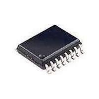
74LV4799PW NXP Semiconductors, 74LV4799PW Datasheet - Page 9

74LV4799PW
Manufacturer Part Number
74LV4799PW
Description
Timers & Support Products 3.3V TIMER NICD AND NIMH CHARGER
Manufacturer
NXP Semiconductors
Datasheet
1.74LV4799D.pdf
(18 pages)
Specifications of 74LV4799PW
Operating Temperature (max)
70C
Operating Temperature (min)
0C
Package Type
TSSOP
Pin Count
16
Mounting
Surface Mount
Mounting Style
SMD/SMT
Package / Case
SOT-403
Lead Free Status / RoHS Status
Compliant
Other names
74LV4799PW,112
1. The oscillator frequency can be calculated by: f + 0.36
2. During blinking.
3. An output signal of four periods will appear in case of discharged batteries and DIS is switched HIGH.
Philips Semiconductors
AC CHARACTERISTICS
GND = 0V; t
NOTES:
APPLICATION INFORMATION
Oscillator.
The frequency will be determined by the external components R
expressions: f +
R
R
R
The charge, discharge and self-discharge times can be calculated as follows:
In the trickle charge mode, the average charge current will be reduced by a factor:
External components range
1998 Apr 20
Charge time + 2
SYMBOL
C
D
S
Timer for NiCd and NiMH chargers
SYMBOL
f
f
f
f
and C1 determine the charge time.
and C1 determine the discharge time.
and C1 determine the self-charge time.
MOLLI
MOLLI
i(
i(max)
i( i )
i(min)
t
t
R
R
LED
LED
d b
deb
C
C
f
f
R
R
C1
C1
/R
/R
S
S
)
D
D
r
Oscillator frequency spread
Oscillator frequency s read
Duty factor at pin 1
Duty factor at in 1
Duty factor at pin 6
Duty factor at in 6
Debounce suppression at pin 9
Debounce su ression at in 9
Maximum frequency at power
sense input
Minimum frequency at power
sense input
= t
f
Resistor range
Resistor range
Resistor range
Resistor range
Capacitor range
Ca acitor range
f
C
R
22
2.5ns; C
C
; Discharge time + 2
0.36
PARAMETER
PARAMETER
C1
q
q
; f +
L
= 50pF
y
y
R
D
0.36
C1
f
; f +
18
D
; Self-discharge time + 2
V
R
CC
1.0
6.0
1.0
6.0
1.0
6.0
1.0
6.0
1.0
6.0
1.0
6.0
S
0.36
V
(V)
CC
1.0
2.0
4.5
6.0
1.0
2.0
4.5
6.0
1.0
2.0
4.5
6.0
C1
(V)
R
Any resistor or capacitor according to
the application information, see note 1
See Note 2
See Note 2
See Note 3
See Note 3
.
y
C1
TEST CONDITIONS
TEST CONDITIONS
TEST CONDITIONS
TEST CONDITIONS
C
, R
D
f
V
, R
27
S
1
9
S
, and C
C1 = 0 22 F
C1 = 0.22 F
C1 = 0 22 F
C1 = 0.22 F
1
. The frequencies can be calculated by the following
1 )
OTHER
3 x R
4 x R
1
g
S
C
5.360
1.150
0.562
0.511
42.20
9.09
4.22
3.32
MIN
MIN
100
100
–11
–9
–
–
–
–
–
–
TYP
+25
T
–4
–2
50
50
50
50
67
65
amb
TYP
+25
T
amb
( C)
MAX
+3
+5
50
50
( C)
no limit
no limit
no limit
no limit
MAX
100
100
100
100
825
825
825
825
MIN
Product specification
74LV4799
0 to +70
MAX
UNIT
kW
kW
kW
kW
kW
kW
kW
kW
pF
pF
F
F
UNIT
kHz
kHz
ms
ms
Hz
Hz
%
%
%
%
%
%


