BZE6-7RNT Honeywell, BZE6-7RNT Datasheet - Page 89
BZE6-7RNT
Manufacturer Part Number
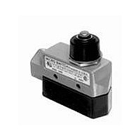
BZE6-7RNT
Description
Basic / Snap Action / Limit Switches Top Plunger Actuator 14 NPT conduit
Manufacturer
Honeywell
Type
Basicr
Specifications of BZE6-7RNT
Pole Throw Configuration
SPDT
Switch Function Configuration
N.O./N.C.
Current Rating (max)
15A
Terminal Type
Screw
Contact Form
SPDT - 1 NC / 1 NO
Contact Rating
15 Amps
Actuator
Plunger
Operating Force
7.78 N to 15.01 N
Termination Style
Screw
Ingress Protection
IP66 / NEMA 1, 3, 4
Actuator Type
Plunger
Brand/series
E6 Series
Current, Rating
0.5 A
Ip Rating
IP54
Material, Contact
Zinc Die-Cast (Housing)
Mounting Type
Side Mount
Number Of Poles
1
Number Of Positions
2
Standards
UL Recognized, CSA Certified, NEMA Approved
Temperature, Operating
-32 to +71 °C
Termination
Screw
Lead Free Status / RoHS Status
Compliant


Basic Switches
Magnetic Blow-out
ELECTRICAL RATING
70
Single-pole
double-throw
unless
otherwise noted
in order guide
*To polarize, connect negative side of line to common terminal. To
achieve the same effect, mount switch with brass screws, using a
non-magnetic barrier (at least
mounting surface.
Dim. Dwg. Fig. 1
Honeywell Sensing and Control
Circuitry
ORDER GUIDE
MT-4R-A28
Catalog Listing
K Rating established with
1
switch non-polarized
10 amps, 125 vac or vdc;
1/4 hp, 125 vac or vdc.
UL Code L 168
Non-polarized:
10 amps res. or 1/4 hp, 125 vdc;
3 amps max. res. 250 vdc.
Polarized*:
10 amps res. or 1/2 hp, 125 vdc;
3 amps max. res., 250 vdc.
⁄
4
thick) between the switch and
Electrical Data and
UL Codes
Pin plunger
SPDT
Recommended For
FEATURES
AVAILABLE TERMINALS
Arc resistant case
Mechanical life of 100,000 operations
— 95% survival
Temperature tolerance to
(82 C)
Mounting interchangeability with Z
switches
UL recognized
Solder (No listing designation)
UL Codes
Electrical
Data and
10 Amps
K
newtons
ounces
3,34-5,0
For application help: call 1-800-537-6945.
12-18
O.F.
180 F
R.F. min.
newtons
ounces
1,39
Characteristics: O.F. – Operating Force;
R.F. – Release Force; P .T. – Pretravel;
O.T. – Overtravel; D.T. – Differential Travel;
O.P . – Operating Position.
5
GENERAL INFORMATION
MT (single-pole double-throw) magnetic
blow-out switches are designed to switch
high capacity (125 and 250 VDC) sys-
tems. An integral magnet around the con-
tact gap protects the contacts by deflect-
ing the arc. Vents between the cover and
housing allow the hot gas to escape.
These switches are designed for the con-
trol of DC motors, solenoids, etc.
P.T. max.
inches
1,02
A28
6-32NC
will accept up to #12 wire.
mm
.04
O.T. min.
inches
.218 Screws
.005
0,13
mm
.004-.007
D.T. max.
0,1-0,18
inches
mm
MT Series
.625 .015
15,9 0,38
inches
O.P .
mm
Related parts for BZE6-7RNT
Image
Part Number
Description
Manufacturer
Datasheet
Request
R

Part Number:
Description:
Basic / Snap Action / Limit Switches Limit Switch E6 ENCLOSURES(BZE6)
Manufacturer:
Honeywell

Part Number:
Description:
Basic / Snap Action / Limit Switches E6 ENCLOSURES(BZE6)
Manufacturer:
Honeywell

Part Number:
Description:
Basic / Snap Action / Limit Switches Limit Switch E6 ENCLOSURES(BZE6)
Manufacturer:
Honeywell

Part Number:
Description:
Basic / Snap Action / Limit Switches Limit Switch E6 ENCLOSURES(BZE6)
Manufacturer:
Honeywell

Part Number:
Description:
Basic / Snap Action / Limit Switches Limit Switch E6 ENCLOSURES(BZE6)
Manufacturer:
Honeywell
Part Number:
Description:
Basic / Snap Action / Limit Switches E6 ENCLOSURES(BZE6)
Manufacturer:
Honeywell

Part Number:
Description:
Basic / Snap Action / Limit Switches Limit Switch E6 ENCLOSURES(BZE6)
Manufacturer:
Honeywell

Part Number:
Description:
Basic / Snap Action / Limit Switches Limit Switch E6 ENCLOSURES(BZE6)
Manufacturer:
Honeywell

Part Number:
Description:
Basic / Snap Action / Limit Switches Limit Switch E6 ENCLOSURES(BZE6)
Manufacturer:
Honeywell

Part Number:
Description:
SWITCH TOP PLUNGER SPDT 15A
Manufacturer:
Honeywell Sensing and Control
Datasheet:
Part Number:
Description:
SWTCH TOP PLNGR SNAP SPDT ENCLSD
Manufacturer:
Honeywell Sensing and Control
Datasheet:

Part Number:
Description:
SWITCH TOP PLNGR SNAP SPDT
Manufacturer:
Honeywell Sensing and Control
Datasheet:
Part Number:
Description:
SWTCH TOP PLNGR SNAP SPDT ENCLSD
Manufacturer:
Honeywell Sensing and Control
Datasheet:
Part Number:
Description:
SWITCH TOP ROLLER ARM SPDT 15A
Manufacturer:
Honeywell Sensing and Control
Datasheet:
Part Number:
Description:
SWITCH TOP ROLLR PLNGR SNAP SPDT
Manufacturer:
Honeywell Sensing and Control
Datasheet: