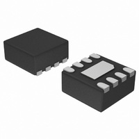
NUF4401MNT1G ON Semiconductor, NUF4401MNT1G Datasheet - Page 4

NUF4401MNT1G
Manufacturer Part Number
NUF4401MNT1G
Description
IC FILTER 4CH EMI ESD PROT 8DFN
Manufacturer
ON Semiconductor
Datasheet
1.NUF4401MNT1G.pdf
(6 pages)
Specifications of NUF4401MNT1G
Resistance (ohms)
200
Capacitance
15pF
Package / Case
8-TDFN Exposed Pad
Resistance In Ohms
200
Lead Free Status / RoHS Status
Lead free / RoHS Compliant
Power (watts)
-
Tolerance
-
Other names
NUF4401MNT1G
NUF4401MNT1GOSTR
NUF4401MNT1GOSTR
Theory of Operation
filtering conveniently into a small package for today’s size
constrained applications. The capacitance inherent to a
typical protection diode is utilized to provide the
capacitance value necessary to create the desired frequency
response based upon the series resistance in the filter. By
combining this functionality into one device, a large number
of discrete components are integrated into one small
package saving valuable board space and reducing BOM
count and cost in the application.
Application Example
is to use the 3 dB cutoff frequency. Utilizing points such as
the 6 dB or 9 dB cutoff frequencies results in signal
degradation in an application. This can be illustrated in an
application example. A typical application would include
EMI filtering of data lines in a camera or display interface.
In such an example it is important to first understand the
signal and its spectral content. By understanding these
things, an appropriate filter can be selected for the desired
application. A typical data signal is pattern of 1’s and 0’s
transmitted over a line in a form similar to a square wave.
The maximum frequency of such a signal would be the
pattern 1-0-1-0 such that for a signal with a data rate of
100 Mbps, the maximum frequency component would be
50 MHz. The next item to consider is the spectral content of
the signal, which can be understood with the Fourier series
supported frequency of a waveform that can be passed
through the filter can be found by dividing the bandwidth by
a factor of three (to obtain the corresponding data rate
multiply the result by two). The following table gives the
bandwidth values and the corresponding maximum
supported frequencies and the third harmonic frequencies.
The NUF4401MN combines ESD protection and EMI
The accepted practice for specifying bandwidth in a filter
From the above paragraphs it is shown that the maximum
100k
1M
Figure 7. Filter Bandwidth
10M
http://onsemi.com
Frequency (Hz)
4
approximation of a square wave, shown below in Equations
1 and 2 in the Fourier series approximation.
order harmonics and to fully construct a square wave n must
go to infinity. However, to retain an acceptable portion of the
waveform, the first two terms are generally sufficient. These
two terms contain about 85% of the signal amplitude and
allow a reasonable square wave to be reconstructed.
Therefore, to reasonably pass a square wave of frequency x
the minimum filter bandwidth necessary is 3x. All ON
Semiconductor EMI filters are rated according to this
principle. Attempting to violate this principle will result in
significant rounding of the waveform and cause problems in
transmitting the correct data. For example, take the filter
with the response shown in Figure 7 and apply three
different data waveforms. To calculate these three different
frequencies, the 3 dB, 6 dB, and 9 dB bandwidths will be
used.
Equation 1:
Equation 2 (simplified form of Equation 1):
x(t) + 1
f
100M
1
Table 2. Frequency Chart
3 dB–100 MHz
6 dB–200 MHz
9 dB–300 MHz
From this it can be seen that a square wave consists of odd
Bandwidth
f
2
x(t) + 1
2
f
3
) 2 p
2
) 2 p
sin(w
−3 dB
1
−6 dB
n + 1
Maximum Supported
S
0
a
t)
−9 dB
1G
33.33 MHz (f
66.67 MHz (f
)
100 MHz (f
Frequency
sin(3w
2n * 1
1
3
0
t)
3
sin((2n * 1)w
1
2
)
)
)
)
10G
sin(5w
5
Third Harmonic
0
t)
Frequency
100 MHz
200 MHz
300 MHz
) AAA
0
t)
(eq. 1)
(eq. 2)


