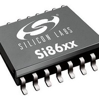
SI8631ED-B-IS Silicon Laboratories Inc, SI8631ED-B-IS Datasheet - Page 13

SI8631ED-B-IS
Manufacturer Part Number
SI8631ED-B-IS
Description
IC ISOLATOR 3CH 5.0KV 16-SOIC
Manufacturer
Silicon Laboratories Inc
Datasheet
1.SI8630.pdf
(36 pages)
Specifications of SI8631ED-B-IS
Number Of Channels
3
Supply Voltage (max)
5 KV
Mounting Style
SMD/SMT
Package / Case
SOIC-16
Lead Free Status / Rohs Status
Lead free / RoHS Compliant
Other names
336-2079-5
Available stocks
Company
Part Number
Manufacturer
Quantity
Price
Part Number:
SI8631ED-B-IS
Manufacturer:
SILICON LABS/芯科
Quantity:
20 000
Part Number:
SI8631ED-B-ISR
Manufacturer:
SILICON LABS/芯科
Quantity:
20 000
Table 5. Regulatory Information*
Table 4. Electrical Characteristics (Continued)
(V
CSA
The Si863x is certified under CSA Component Acceptance Notice 5A. For more details, see File 232873.
61010-1: Up to 600 V
60950-1: Up to 600 V
age.
60601-1: Up to 125 V
VDE
The Si863x is certified according to IEC 60747-5-2. For more details, see File 5006301-4880-0001.
60747-5-2: Up to 1200 V
60950-1: Up to 600 V
age.
UL
The Si863x is certified under UL1577 component recognition program. For more details, see File E257455.
Rated up to 5000 V
*Note: Regulatory Certifications apply to 3.75 kV
Parameter
All Models
Output Rise Time
Output Fall Time
Peak Eye Diagram Jitter
Common Mode
Transient Immunity
Enable to Data Valid
Enable to Data Tri-State
Startup Time
Notes:
DD1
1. The nominal output impedance of an isolator driver channel is approximately 50 , ±40%, which is a combination of
2. t
3. Start-up time is the time period from the application of power to valid data at the output.
= 2.5 V ±5%, V
Regulatory Certifications apply to 5.0 kV
For more information, see "5. Ordering Guide" on page 26.
the value of the on-chip series termination resistor and channel resistance of the output driver FET. When driving loads
where transmission line effects will be a factor, output pins should be appropriately terminated with controlled
impedance PCB traces.
the same supply voltages, load, and ambient temperature.
PSK(P-P)
3
is the magnitude of the difference in propagation delay times measured between different units operating at
DD2
RMS
RMS
RMS
RMS
RMS
= 2.5 V ±5%, T
isolation voltage for basic protection.
peak
reinforced insulation working voltage; up to 600 V
reinforced insulation working voltage; up to 1000 V
reinforced insulation working voltage; up to 380 V
reinforced insulation working voltage; up to 1000 V
for basic insulation working voltage.
A
Symbol
t
= –40 to 125 ºC)
JIT(PK)
CMTI
t
t
t
en1
en2
SU
t
t
r
f
RMS
RMS
rated devices which are production tested to 6.0 kV
Test Condition
V
rated devices which are production tested to 4.5 kV
See Figure 2
See Figure 2
See Figure 7
See Figure 1
See Figure 1
I
C
C
= V
L
L
Rev. 1.1
= 15 pF
= 15 pF
DD
or 0 V
Min
35
—
—
—
—
—
—
RMS
RMS
RMS
RMS
basic insulation working voltage.
basic insulation working voltage.
basic insulation working volt-
basic insulation working volt-
Si8630/31/35
Typ
350
2.5
2.5
6.0
8.0
50
15
RMS
RMS
for 1 sec.
Max
4.0
4.0
for 1 sec.
—
—
11
12
40
kV/µs
Unit
µs
ns
ns
ps
ns
ns
13


