41F Cinch Connectors, 41F Datasheet - Page 4
41F
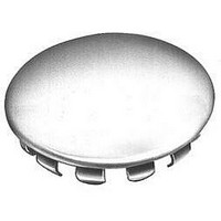
Manufacturer Part Number
41F
Description
PLUG BUTTON .875" HOLE
Manufacturer
Cinch Connectors
Type
Body Plugr
Datasheet
1.41C.pdf
(282 pages)
Specifications of 41F
Color
Natural
Hole Diameter
0.875" (22.23mm)
Flange Diameter
1.062" (26.97mm)
Rohs Compliant
YES
Lead Free Status / RoHS Status
Lead free / RoHS Compliant
Panel Thickness
-
Lead Free Status / RoHS Status
Lead free / RoHS Compliant
Available stocks
Company
Part Number
Manufacturer
Quantity
Price
Company:

Part Number:
41F-1Z-C2-1
Manufacturer:
HGF
Quantity:
6
Company:
Part Number:
41FVX-RSM1-GSAN-G-ETF(S)
Manufacturer:
SHUN
Quantity:
994
Company:
Part Number:
41FXW-RSMI-G-G-TB
Manufacturer:
N/A
Quantity:
320


The unique construction of the CIN::APSE contact
provides superior mechanical and electrical performance.
It is constructed of randomly wound molybdenum wire that
is formed into a cyclindrical shape. Standard CIN::APSE
contact diameters are 0.020" and 0.040".
Mechanical
• Small form factor (0.020" diameter by 0.32" min. high)
• Low compression force (approx. 2.5 oz. min. per contact)
• Multiple beam structures
• Several points of contact per button
• Extremely lightweight
• Natural wiping action
Electrical
• Short signal path
• Very low inductance and resistance
• Signal integrity tested in the GHz range
The basic button contact
configuration consists of a single
button installed in our patented
“hourglass” design.
The hourglass cavity retains the
CIN::APSE contact securely.
Typically 0.003" protrudes from the
top and the bottom of the insulator.
CIN::APSE
High-Speed Interconnect Technology
THE BUTTON CONTACT
CIN::APSE APPLIED
®
Step 1:
Using alignment features,
position the CIN::APSE
connector between a LGA chip
package and PCB or two PCBs
that have matching footprints.
1-2
Typical CIN::APSE Applications
• LGA package I/O to PC board (IC packages,
• PC board to PC board (parallel processors,
• Flex circuit to PC board (rigid flex, harnessing)
• Flex circuit to ceramic (chip to harness)
multi-chip modules)
enhancement/mezzanine cards)
Step 2:
Add Z-Axis compression
and secure.
Call Toll Free: 1 (800) 323-9612
Related parts for 41F
Image
Part Number
Description
Manufacturer
Datasheet
Request
R

Part Number:
Description:
Standard Card Edge Connectors CINCH BLK CARD GUIDE
Manufacturer:
Cinch Connectors

Part Number:
Description:
Automotive Connectors 18 Pos Black
Manufacturer:
Cinch Connectors
Part Number:
Description:
Automotive Connectors 30 Pos Black
Manufacturer:
Cinch Connectors
Part Number:
Description:
Automotive Connectors 30 Pos Black mates only w/ 60 Pin
Manufacturer:
Cinch Connectors
Part Number:
Description:
D-Subminiature Connectors 25C PLG S/CUP BASIC-D SERIES
Manufacturer:
Cinch Connectors

Part Number:
Description:
D-Subminiature Connectors 9C 2PC PLSTC BCKSHLL
Manufacturer:
Cinch Connectors

Part Number:
Description:
TERMINAL BLOCK JUMPER TYPE F
Manufacturer:
Cinch Connectors
Datasheet:
Part Number:
Description:
D-Subminiature Connectors MCHNED PIN 20-24AWG
Manufacturer:
Cinch Connectors
Datasheet:
Part Number:
Description:
Terminal Block,4 Contacts,0.44 Pitch
Manufacturer:
Cinch Connectors
Datasheet:

Part Number:
Description:
Terminal Block,8 Contacts,0.375 Pitch
Manufacturer:
Cinch Connectors
Datasheet: