H7ET-NFV-B Omron, H7ET-NFV-B Datasheet - Page 24
H7ET-NFV-B
Manufacturer Part Number
H7ET-NFV-B
Description
COUNTER TIME 999KHRS AC/DC IN
Manufacturer
Omron
Series
H7ETr
Specifications of H7ET-NFV-B
Operating Mode
Accumulative
Output Type
None
Voltage - Supply
None Required (Battery Included)
Termination Style
Screw Terminal
Display Type
LCD Non-Backlit
Timing Range
999999.9 h, 3999 d 23.9 h
No. Of Digits / Alpha
7
Digit Height
8.6mm
Operating Temperature Range
-10°C To +55°C
Signal Input Type
AC/DC Voltage
Ip/nema Rating
IP66 / NEMA 4
Panel Cutout Height
22.2mm
Mounting Type
Panel
Panel Cutout Width
45mm
Rohs Compliant
Yes
Lead Free Status / RoHS Status
Lead free / RoHS Compliant
Lead Free Status / RoHS Status
Lead free / RoHS Compliant, Lead free / RoHS Compliant
Other names
H7ET-FBV
H7ETNFVB
Z875
H7ETNFVB
Z875


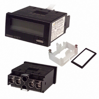
Connections
■ Terminal Arrangement
■ Connections
Power Supply and Battery Connections
Battery Connections
When designing a circuit, keep the power wiring connections shorter
than 50 mm. Refer to the connection diagram above for the proper
wiring polarity.
The life expectancy of a battery power supply can be calculated by
the following formula:
t = A/l
Where,
t:
A: Battery capacity (mAh)
l
Example:
Battery life when using a 3-V lithium battery with a capacity of
1,200 mAh for the H7E@-N@P.
t = 1,200 [mAh]/20 × 10
The battery capacity varies depending on the type of battery used;
oxidized silver, mercury, or lithium battery.
Voltage Division of Power Supply Circuit
When necessary, the voltage from the battery may be divided by
resistances:
When doing so, however, ensure that the following equation bal-
ances:
E (V) × R
Allow a current high enough to flow through R
N@P receives sufficient current.
C is a film capacitor, of about 0.1 µF, and is intended to absorb noise
induced by the power lines.
Keep the wiring between the H7E@-N@P and R
possible (within 50 mm).
H7EC-N@P
c
R
R
: H7E@-N@P current consumption (mA)
1
2
Life expectancy of battery (h)
c
Reset
input
R
2
/ (R
1
+ R
H7E@-N@P
2 kΩ
3 kΩ
2
) = 3 V
–3
5 V
[mA] = 60,000 hours (approx. 6.8 years)
H7E@-N@P
3-V battery
3-VDC external
power supply
9.1 kΩ
3 kΩ
Count
input
12 V
E
1
so that the H7E@-
2
or C as short as
33 kΩ
4.7 kΩ
24 V
H7ET-NP
Reset
input
Backup Circuit for Protection Against Power
Failure
Use a diode (D) having a forward voltage as small as possible (0.1 V
max. at I
Determine the ratio of R
age of the diode to be used. Be aware that when the power supplied
to the H7E@-N@P has dropped to less than the voltage of the
backup circuit, the battery will discharge.
To protect the circuit against a momentary power failure, an alumi-
num electrolyte capacitor can be used in place of a battery, as shown
below:
When a capacitor is used, its backup time can be calculated by the
following formula:
t = C (V
Where,
t:
C: Capacitance (µF)
V
V
I
Example:
Backup time by an aluminum electrolytic capacitor of 100 µF. (Mini-
mum operating voltage of H7E@-N@P is 2.6 V.)
t = 100 µF × (3–2.6 V)/20 µA = 100 × 0.40/20 = 2.0 seconds
Note that the above calculation provides an approximate value,
which varies depending on the environment under which the Counter
is used and also on the type of capacitors used. Provide some allow-
ance in selecting capacitors.
Keep the wiring between the H7E@-N@P and R
possible (within 50 mm).
c
: H7E@-N@P current consumption (µA)
1
2
: Supply voltage before power failure (V)
: Minimum operating voltage of H7E@-N@P (V)
Backup time (s)
1
F
– V
of 20 µA).
2
) / I
c
H7E@-N@P
H7E@-N@P
3-VDC external
power supply
1
to R
Timer
input
2
in accordance with the forward volt-
3-V
bat-
tery
Backup
circuit
Backup
circuit
H7E@-N@P
2
or C as short as
24