CUB3L000/A Red Lion Controls, CUB3L000/A Datasheet - Page 2
CUB3L000/A
Manufacturer Part Number
CUB3L000/A
Description
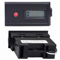
COUNTER GEN PURP W/BATT CUB3L000
Manufacturer
Red Lion Controls
Series
CUB3r
Datasheet
1.CUB3L000A.pdf
(2 pages)
Specifications of CUB3L000/A
Count Rate
100Hz
Number Of Digits/alpha
6
Input Type
Switch Closure or Transistor Switch
Voltage - Supply
None Required (Battery Included)
Display Type
LCD Non-Backlit
Lead Free Status / RoHS Status
Lead free / RoHS Compliant
Output Type
-
Other names
CUB3L
CUB3L000
RLC04
CUB3L000
RLC04
Available stocks
Company
Part Number
Manufacturer
Quantity
Price
Company:

Part Number:
CUB3L000/A
Manufacturer:
Red Lion Controls
Quantity:
135


EMC COMPLIANCE INSTALLATION
listed in the specifications. Compliance to the EMC standards was demonstrated
by means of a test set-up using the following installation methods:
1. Unit installed in a metal panel mounted to an open aluminum rack connected
2. Shielded (screened) cables for Signal and Control inputs with shield drain
every unit installation. For the purpose of EMC testing, the input line on the unit
was connected with 25 feet (8 m) of cable. In extremely high EMI environments,
additional measures may be needed. Cable length, routing and shield termination
are very important and can mean the difference between a successful installation
or a troublesome installation.
ADDITIONAL EMC INSTALLATION GUIDELINES
ElectroMagnetic Interference (EMI), proper installation and wiring methods
must be followed to ensure compatibility in each application. The type of the
electrical noise, source or coupling method into the unit may be different for
various installations. Listed below are some additional EMC guidelines for
successful installation in an industrial environment.
1. Use shielded (screened) cables for all Signal and Control inputs. The shield
2. Never run Signal or Control cables in the same conduit or raceway with AC
1.10 (28)
DIMENSIONS
This unit complies with the Electromagnetic Compatibility (EMC) standards
to earth ground (protective earth).
wire connected to earth ground at the mounting panel only.
It should be noted that the methods listed above may not be necessary for
Although this unit is designed with a high degree of immunity to
(screen) pigtail connection should be made as short as possible. The
connection point for the shield depends somewhat upon the application.
Listed below are the recommended methods of connecting the shield, in order
of their effectiveness.
a. Connect the shield only at the panel where the unit is mounted to earth
b. Connect the shield to earth ground at both ends of the cable, usually when
c. Connect the shield to common of the unit and leave the other end of the
power lines, conductors feeding motors, solenoids, SCR controls, and
heaters, etc. The cables should be run in metal conduit that is properly
grounded. This is especially useful in applications where cable runs are long
and portable two-way radios are used in close proximity or if the installation
is near a commercial radio transmitter.
BEZEL
Belden #8451 - 2 conductor, #22 AWG twisted
pair w/ foil shield and drain wire
ground (protective earth).
the noise source frequency is above 1 MHz.
shield unconnected and insulated from earth ground.
(MAX) BEHIND BEZEL
0.95 (24.2)
BODY DEPTH
BODY
2.09 (53)
Multi-conductor Cable
BEZEL
1.72 (43.7)
1.94
BODY
In inches (mm) &
(49.3)
PANEL CLASP
EACH SIDE)
(ONE ON
INSTALLATION
Count and Reset Inputs
Function Used For
0.150 (3.8) BEZEL
PROTRUSION FROM
PANEL FRONT
COMMON
(BLK)
COUNT INPUT
LEADS 22GA
12 LONG (WHT)
3. Signal or Control cables within an enclosure should be routed as far away as
4. In extremely high EMI environments, the use of external EMI suppression
5. Long cable runs are more susceptible to EMI pickup than short cable runs.
TROUBLESHOOTING
company numbers listed.
ELECTRICAL CONNECTIONS &
COUNT INPUTS
switch contacts or solid-state switches (NPN or PNP transistors) as shown
in the diagrams below. Reed switches, mercury-wetted contacts, snap-action
limit switches, and silver alloy contacts with wiping action are usually
satisfactory choices for mechanical switch input. Heavy “clapper-type”
contacts such as used in contactors or large machine tool relays, tungsten
contacts, or brush type contacts are not recommended as count input devices.
INSTALLATION ENVIRONMENT
maximum operating temperature and provides good air circulation. Placing
the unit near devices that generate excessive heat should be avoided.
product. Do NOT use solvents. Continuous exposure to direct sunlight may
accelerate the aging process of the bezel.
the keypad of the unit.
PANEL CUT-OUT
PANEL THICKNESS
possible from contactors, control relays, transformers, and other noisy
components.
devices, such as ferrite suppression cores, is effective. Install them on Signal
and Control cables as close to the unit as possible. Loop the cable through the
core several times or use multiple cores on each cable for additional protection.
The following EMI suppression devices (or equivalent) are recommended:
Ferrite Suppression Cores for signal and control cables:
Therefore, keep cable runs as short as possible.
For further technical assistance, contact technical support at the appropriate
1" x 2" or 25 mm x 50 mm
0.05" to 0.125"
The CUB3Ls can be supplied with count input signals from mechanical
The unit should be installed in a location that does not exceed the
The bezel should be cleaned only with a soft cloth and neutral soap
Do not use tools of any kind (screwdrivers, pens, pencils, etc.) to operate
Fair-Rite # 0443167251 (RLC #FCOR0000)
TDK # ZCAT3035-1330A
Steward #28B2029-0A0
COUNTER
(+)CNT. IN (WHT)
RST.(BLUE)
(-)COMMON(BLK)
CONTACT
SWITCH
COMMON
TRANSISTOR
NPN O.C.
COUNT
INPUT
LEADS
STRAIN
RELIEF
TRANSISTOR
PNP O.C.