H7ET-NFV1 Omron, H7ET-NFV1 Datasheet - Page 9
H7ET-NFV1
Manufacturer Part Number
H7ET-NFV1
Description
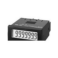
TIME COUNTER LCD AC/DC-INPUT
Manufacturer
Omron
Series
H7ETr
Specifications of H7ET-NFV1
Operating Mode
Accumulative
Output Type
None
Voltage - Supply
None Required (Battery Included)
Termination Style
Screw Terminal
Display Type
LCD Non-Backlit
Lead Free Status / RoHS Status
Lead free / RoHS Compliant
Other names
H7ETNFV1
Available stocks
Company
Part Number
Manufacturer
Quantity
Price
Company:

Part Number:
H7ET-NFV1-B
Manufacturer:
Omron Electronics Inc-IA Div
Quantity:
135


Precautions
H7ET
J Y92S-36 REPLACEMENT (LITHIUM)
This product has a built-in lithium battery. Do not short-circuit
the + and - - terminals, charge, disassemble, deform, or expose
the battery to fire. The battery may explode (break), catch fire,
or cause liquid leakage.
Do not use any battery other than the specified one (Y92S-36).
Using another battery may cause liquid leakage or breakage,
resulting in malfunction or injury.
If a voltage other than the rated one is applied, internal
elements may be damaged.
Do not use the Counter in the following places:
•
•
•
!
!
!
BATTERY (3 V)
Locations subject to direct sunlight.
Locations subject to corrosive gases.
Locations subject to dust.
WARNING
Caution
Caution
7.7
24.5 dia.
9
J BEFORE USE
An insulation sheet has been inserted to maintain the quality of
the Totalizer in the event of a long period without use. Be sure to
remove this sheet before attempting to use the product.
Remove the insulation sheet and press the Reset Key on the
front panel of the Counter. (With the H7ET-N,-NV(-H),-NV1(-H),
models, “0” or “0.0” will be displayed after 1 s.)
Switch settings on the Counter must be performed before
mounting it to a control panel.
Do not use the Counter in locations subject to:
SSevere changes in temperature.
SCondensation as the result of high temperatures.
J MOUNTING PRECAUTIONS FOR
Although the operating section is watertight (conforming to
NEMA 4, IP66), a rubber gasket is provided to avoid water
leakage through the gap between the Counter and panel cutout.
Unless this rubber gasket is tightly squeezed on, water may
permeate inside the panel. For this reason, be sure to tighten the
screws for fixing the panel-mounting bracket.
Screw for the Panel-Mounting Bracket
The wider side must
face the panel.
PANEL- MOUNTING
Panel
Insulation Sheet
Adapter
Adapter screw section
Tighten the screw until the
distance is within the range
shown above.
Reset Key
0.5 to 1 mm
H7ET