H7GP-TB Omron, H7GP-TB Datasheet - Page 3
H7GP-TB
Manufacturer Part Number
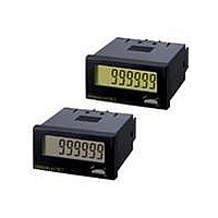
H7GP-TB
Description
COUNTER TIME LCD 6DIGT 100-240V
Manufacturer
Omron
Type
Time Totalizerr
Specifications of H7GP-TB
Operating Mode
Accumulative
Output Type
*
Voltage - Supply
*
Termination Style
Screw Terminal
Display Type
*
Input Type
*
Number Of Digits/alpha
*
Count Rate
*
Voltage Rating
100 V to 240 V
Mounting
Panel
Counting Method
Accumulative
Size
80 mm L x 44 mm W x 22 mm H
Features
NEMA 4 protection using Y92S-32 rubber gasket supplied with unit, NPN and PNP operations
Time Range
99999.9hr
Power Consumption
6.5VA
Reset Time
20ms
Character Size
8.5mm
Height
24mm
Mounting Type
Panel
Supply Voltage Min
100VAC
Color
Black
Connector Type
Screw Terminals
Width
48mm
Depth
80mm
No. Of Digits / Alpha
6
Rohs Compliant
Yes
Lead Free Status / RoHS Status
Lead free / RoHS Compliant
Lead Free Status / RoHS Status
Lead free / RoHS Compliant, Lead free / RoHS Compliant
Other names
H7GPTB


■ Characteristics
Insulation resistance
Dielectric strength
Impulse withstand voltage 3 kV (between power terminals) (1 kV for 12-to-24-VDC models)
Noise immunity
Static immunity
Vibration resistance
Shock resistance
Ambient temperature
Ambient humidity
EMC
Approved standards
Case color
Weight
http://www.ia.omron.com/
100 MΩ min. (at 500 VDC)
2,000 VAC, 50/60 Hz for 1 min between current-carrying terminal and exposed non-current-carrying metal parts
(AC model)
1,000 VAC, 50/60 Hz for 1 min between current-carrying terminal and exposed non-current-carrying metal parts
(DC model)
2,000 VAC, 50/60 Hz for 1 min between power terminals and control input terminals (AC model)
4.5 kV (between current-carrying terminal and exposed non-current-carrying metal parts) (1.5 kV for 12-to-24-VDC
models)
±1.5 kV (between AC power terminals), ±480 V (between DC power terminals),
±480 V (between input terminals);
square-wave noise by noise simulator (pulse width: 100 ns/1 μs, 1-ns rise)
Display:
DIP switch: Malfunction:4 kV
Destruction: 10 to 55 Hz with 0.75-mm single amplitude, four cycles each in three directions (8 minutes per cycle)
Malfunction: 10 to 55 Hz with 0.5-mm single amplitude, four cycles each in three directions (8 minutes per cycle)
Destruction: 294 m/s
Malfunction: 196 m/s
Operating: –10°C to 55°C (with no icing)
Storage:
Operating: 35% to 85%
(EMI)
Emission Enclosure:
Emission AC Mains:
(EMS)
Immunity ESD:
Immunity RF-interference:
Immunity Conducted Disturbance: EN61000-4-6: 10 V (0.15 to 80 MHz) (according to EN61000-6-2)
Immunity Burst:
Immunity Surge:
Immunity Voltage Dip/Interruption: EN61000-4-11: 0.5 cycle, 100% (rated voltage)
UL508, CSA22.2 No.14, conforms to EN61010-1, VDE0106/P100
Rear section: Gray smoke; Front section: 5Y7/1 (light gray) or N1.5 (black)
Approx. 75 g
–25°C to 65°C (with no icing)
Malfunction:8 kV
Destruction:15 kV
Destruction:8 kV
2
2
each in three directions
each in three directions
EN61326
EN55011 Group 1 class A
EN55011 Group 1 class A
EN61326
EN61000-4-2: 4 kV contact discharge (level 2)
EN61000-4-3: 10 V/m (Amplitude-modulated, 80 MHz to 1 GHz) (level 3);
EN61000-4-4: 2 kV power-line (level 3);
EN61000-4-5: 1 kV line to lines (power and output lines) (level 2);
(c)Copyright OMRON Corporation 2007 All Rights Reserved.
8 kV air discharge (level 3)
10 V/m (Pulse-modulated, 900 MHz ±5 MHz) (level 3)
2 kV I/O signal-line (level 4)
2 kV line to ground (power and output lines) (level 3)
H7GP
3