LD400400 Red Lion Controls, LD400400 Datasheet - Page 7
LD400400
Manufacturer Part Number
LD400400
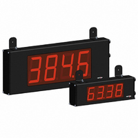
Description
COUNTER 4 DIGIT 4.0" 120VAC RED
Manufacturer
Red Lion Controls
Series
LDr
Type
Counterr
Specifications of LD400400
Count Rate
35kHz
Number Of Digits/alpha
4
Input Type
Voltage
Voltage - Supply
11 V ~ 16 VDC, 85 V ~ 250 VAC
Display Type
LED Red
No. Of Digits / Alpha
4
Digit Height
101mm
Power Consumption
26VA
Counting Speed
25kHz
Operating Temperature Range
0°C To +50°C
Signal Input Type
Pulse
Character Size
4"
Ip/nema Rating
IP65 / NEMA 4X
Connection Type
Wire Leads
Dimensions
20"L×2.25"W×7.875"H
Display Digit Height
4 "
Function
Counter
Material, Casing
Aluminum
Number Of Digits
6
Primary Type
Electronic
Special Features
RS485/RS232 Communications
Termination
Terminal Block
Voltage, Supply
85 to 250/11 to 16 VAC/VDC
Counter Supply Voltage
85-250VAC/11-16VDC
Rohs Compliant
Yes
Lead Free Status / RoHS Status
Lead free / RoHS Compliant
Output Type
-
Lead Free Status / Rohs Status
RoHS Compliant part
Other names
RLC118


MODULE MENU (PAR KEY)
module discussion). The
to be changed, without changing the programming of preceding parameters.
After completing a module, the display will return to
may continue by accessing additional modules.
SELECTION / VALUE ENTRY
the selections/value for that parameter. The
move through the selections/values for that parameter. Pressing the
stores and activates the displayed selection/value. This also advances the meter to
the next parameter.
right most digit). Pressing the
can hold the
will select the next digit to the left. Pressing the
move to the next parameter.
PROGRAMMING MODE EXIT (PAR KEY)
displayed. This will commit any stored parameter changes to memory and return
the meter to the Display Mode. (If power loss occurs before returning to the
Display Mode, verify recent parameter changes.)
if assigned to Counter A. The selection will also affect Counter A scale
factor calculations.
mode or batch counter).
actions are shown in the boxes below. For simple counting applications, it is
recommended to use Count with Direction for the count mode. Simply leave the
direction input unconnected.
5.1 MODULE 1 - I
Each module has a separate module menu (which is shown at the start of each
For each parameter, the display alternates between the present parameter and
For numeric values, the value is displayed with one digit flashing (initially the
The Programming Mode is exited by pressing the
This selects the decimal point position for Counter A and the setpoint value,
Shaded area selections only apply when Counter B is enabled (Dual Count
Select the count mode that corresponds with your application. The input
Note: The Rate indicator signal is derived from Input A in all count modes.
DISPLAY
COUNTER A DECIMAL POINT POSITION
PAR
RST
INP Ab
1-INP
Count with Direction
Rate/Counter
Dual Counter
Quadrature x1
Quadrature x2
Quadrature x4
2 Input Add/Add
2 Input Add/Subtract
Count
Mode
key and the digit will automatically scroll. The
PAR
MODE
COUNT MODE
key is pressed to advance to a particular parameter
RST
Decimal Point
Counter A
A-dPt
key increments the digit by one or the user
INPUT A ACTION
Counter A Add
Counter A Add
Counter A Add
Decimal Point
SEL and RST
Counter A
b-dPt
Rate only
Counter B
Count A
Count A
Count A
PAR
Dual Count or Batch
Scale Factor
A-Scf
Counter A
key will enter the value and
NPUT
PAR
Only
Counter A Direction
Counter A Subtract
key with
INPUT B ACTION
Counter B Add
Scale Factor
Counter A Add
Counter A Add
b-ScF
keys are used to
Counter B
. Programming
PARAMETER MENU
S
Quad A
Quad A
Quad A
SEL
Reset Action
ETUP
A-rSt
PAR
Counter A
key,
key
Counter Reset
at Power-up
r P-UP
P
7
Count Direction
ARAMETERS
PROGRAMMING TIPS
When programming is complete, it is recommended to record the parameter
programming and lock out parameter programming with the user input or
programming security code.
FACTORY SETTINGS
encountering programming problems.
ALTERNATING SELECTION DISPLAY
appear. This is used to illustrate the display alternating between the parameter
on top and the parameter’s Factory Setting on the bottom. In most cases,
selections and values for the parameter will be listed on the right.
desired process value. A scale factor of 1.0000 will result in the display of the
actual number of input counts. (Details on scaling calculations are explained at
the end of this section.)*
This reset action applies to all Counter A resets, except a Setpoint generated
Counter Auto Reset programmed in Module 4.
Count Mode parameter chart.
A-dir
Counter A
It is recommended to start with Module 1 for counting or Module 2 for rate.
Factory Settings may be completely restored in Module 3. This is useful when
In the explanation of the modules, the following dual display with arrows will
The number of input counts is multiplied by the scale factor to obtain the
When Counter A is reset, it returns to Zero or Counter A Count Load value.
Reverse (
USrINP
User Input
Parameter
Indicates Program Mode Alternating Display
Function
) switches the normal Counter A count direction shown in the
COUNTER A COUNT DIRECTION
Count Load
Cnt Ld
Counter A
COUNTER A SCALE FACTOR
COUNTER A RESET ACTION
Value
Factory Settings are shown.
(
Dual Count or
USrASN
Batch Only
Assignment
User Input
Batch Count
b-bAt
Counter B
to
Enable
)
Selection/Value
Pro