LD4006P0 Red Lion Controls, LD4006P0 Datasheet - Page 5
LD4006P0
Manufacturer Part Number
LD4006P0
Description
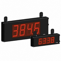
COUNTER 6 DIGIT DUAL 4.0" RED
Manufacturer
Red Lion Controls
Series
LDr
Type
Counterr
Specifications of LD4006P0
Count Rate
35kHz
Number Of Digits/alpha
6
Input Type
Voltage, Switch Closure, Transistor Switch
Output Type
Relay and RS232/RS485
Voltage - Supply
11 V ~ 16 VDC, 85 V ~ 250 VAC
Display Type
LED Red
No. Of Digits / Alpha
6
Digit Height
101mm
Power Consumption
26VA
Counting Speed
25kHz
Operating Temperature Range
0°C To +50°C
Signal Input Type
Pulse
Character Size
4"
Ip/nema Rating
IP65 / NEMA 4X
Accuracy
±0.01% %
Connection Type
Wire Leads
Dimensions
26"L×2.25"W×7.875"H
Display Digit Height
4 "
Function
Counter
Material, Casing
Aluminum
Number Of Digits
6
Primary Type
Electronic
Range, Measurement
0 to 99999
Special Features
RS485/RS232 Communications
Termination
Terminal Block
Voltage, Supply
85 to 250/11 to 16 VAC/VDC
Counter Supply Voltage
85-250VAC/11-16VDC
Rohs Compliant
Yes
Lead Free Status / RoHS Status
Lead free / RoHS Compliant


terminal block TBB located inside the unit on the right side.
different Count Modes. The Count Mode selected determines the action of
Inputs A and B. Section 5.1, Input Setup Parameters, provides details on count
mode selection and input action.
3.4 INPUT WIRING
3.5 SERIAL WIRING
unit on the left side for the LD2 and on the right side for the LD4.
Magnetic Pickup
Current Sinking Output
Switch or Isolated Transistor; Current Sink
TBD
The Large Display has two signal inputs, A and B. These inputs are wired to
Programmable models LD2006P0 and LD4006P0 provide a choice of eight
ON
ON
The serial connections are made via terminal block TBD located inside the
1
1
ON
1
2
2
2
*
3 4
3 4
3 4
Switch position is application dependent.
TBB
TBB
TBB
COMM
Terminal 1: Input A
Terminal 3: Input B
Terminal 2: Input Common
CAUTION: User common is NOT isolated from input common. In order to preserve the safety of the meter application, the DC common must be suitably
RXD
TXD
RESET/USER
RESET/USER
RESET/USER
INP COMM
INP COMM
B
INP COMM
A
isolated from hazardous live earth referenced voltage; or input common must be at protective earth ground potential. If not, hazardous voltage may
be present at the User Input and Input Common terminals. Appropriate considerations must then be given to the potential of the input common with
respect to earth ground.
COMM
COMM
COMM
COMM
COMM
COMM
INP A
1
2
3
4
5
+EXC
INP A
+EXC
INP A
+EXC
INP B
INP B
INP B
232
1
2
3
4
5
6
7
485
1
2
3
4
5
6
7
1
2
3
4
5
6
7
MAGNETIC PICKUP
NPN
O.C.
Input A
Input A
Input A
AC Inputs From Tach Generators, Etc.
Current Sourcing Output
Switch or Isolated Transistor; Current Source
ON
ON
ON
1 2 3
1 2 3 4
1 2 3
4
TBB
TBB
4
TBB
RESET/USER
RESET/USER
RESET/USER
INP COMM
INP COMM
INP COMM
COMM
COMM
COMM
COMM
INP A
+EXC
COMM
COMM
INP B
INP A
+EXC
INP B
INP A
+EXC
INP B
1
2
3
4
5
6
7
1
2
3
4
5
6
7
5
5
6
7
1
2
3
4
Resistor to
limit current
to 2.5 mA MAX.
Mode only. Input A accepts the count signal, while Input B controls the count
direction (up/down).
Switch 8 to the ON position (See Section 2.0, Setting the DIP Switches). For
programmable models, this only applies in Count with Direction mode.
All other models are non-programmable and provide Count with Direction
Input B can also be used to adjust the LED display intensity by setting DIP
AC
PNP
O.C.
Input A
Input A
Input A
Shaded areas not recommended for counting applications.
Two Wire Proximity, Current Source
Interfacing With TTL
Current Sink Output; Quad/Direction
LD2006P0 and LD4006P0 only.
ON
ON
ON
1 2
1 2 3 4
1 2 3 4
3 4
TBB
TBB
TBB
RESET/USER
RESET/USER
RESET/USER
INP COMM
INP COMM
INP COMM
COMM
COMM
COMM
COMM
INP A
INP B
INP A
+EXC
COMM
COMM
INP B
+EXC
INP A
INP B
+EXC
1
2
3
4
5
6
7
1
2
3
4
5
6
7
1
2
3
4
5
6
7
2.2 kΩ
+5 V
COMMON
Input A
Input A