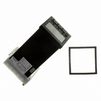
H7CX-AW AC100-240 Omron, H7CX-AW AC100-240 Datasheet - Page 19

H7CX-AW AC100-240
Manufacturer Part Number
H7CX-AW AC100-240
Description
COUNTER DIGITAL 12VDC 2 STAGE
Manufacturer
Omron
Series
H7CXr
Datasheet
1.H7CX-AS_AC100-240.pdf
(63 pages)
Specifications of H7CX-AW AC100-240
Count Rate
30Hz or 5kHz Selectable
Number Of Digits/alpha
6
Input Type
Voltage, Switch Closure, Transistor Switch
Output Type
Switch Closure
Voltage - Supply
100 V ~ 240 V
Display Type
LCD Programmable Color
Lead Free Status / RoHS Status
Lead free / RoHS Compliant
Other names
H7CXAWAC100240
Z2740
Z2740
Settings for All Functions
Note: At the time of delivery, the H7CX is set to the 1-stage counter (2-stage counter for H7CX-AW@/-A4W@ models) configuration. When using
as a 2-stage (or 1-stage) counter, total and preset counter, batch counter, or dual counter, switch to the configuration using the procedure
given on page 36.
Settings that cannot be performed with the DIP switch are performed with the operation keys.
See note 1.
3 s min.
Power ON
3 s min.
See note 2.
Input mode
Output mode
See note 6.
One-shot
output
time
Counting
speed
Reset input
signal
width
Decimal
point
position
Prescale
value
NPN/PNP
input mode
Display color
Output
allocation
Key protect
level
See note 3.
For details on operations and display in run mode, refer to page 22.
The display depends on the configuration used.
The characters displayed in reverse video are the default settings.
When performing settings with operation keys only, set pin1 of the DIP switch to OFF (factory setting).
If pin 1 of the DIP switch is set to ON, the setting items indicated by
Set each setting item using the
See note 7.
See note 7.
Note: 1. If the mode is switched to the function setting mode during operation, operation will
Note: 5. Display only when the input mode is UP/DOWN A, B,
See note 4.
Note: Displayed only when the output mode is C, R, K-1, P,
Note: Displayed for terminal-block models (except H7CX-A11@) only.
Note: Displayed for H7CX-AU@ models only.
(NPN
input)
(N)
(0.01s)
(0.001)
(Red)
(30Hz)
(20ms)
(KP-1)
(UP)
Note 4: Displayed for output modes other than K-2, D, L, and H only.
2. Changes made to settings in function setting mode are enabled for the first time when the
No decimal
point
Q, A, or K-2.
mode is changed to run mode. Also, when settings are changed, the counter is reset
(present value initialized and output turned OFF) on returning to run mode.
continue.
or C with 6-digit models (with H7CX-AU@/-AW@
models only for H).
(F)
(0.50s) (99.99s)
∼
See note 4.
(Green)
(DOWN) (UP/DOWN A) (UP/DOWN B) (UP/DOWN C)
(PNP
input)
(1ms)
(1.000)
(KP-2)
(5kHz)
(C)
(Red-green) (Green-red)
∼
(R)
(99.999)
(KP-3)
One digit after
decimal point
(K-1)
r
[9.999]
(KP-4)
r
(P)
keys. (
(Q)
(KP-5)
r
Two digits after
decimal point
(A)
key only for 6-digit models)
See note 5.
(K-2)
See note 5.
(D)
Note 7: The displays for 4-digit models are shown inside
Note 6:
When using as a 2-stage counter:
When using as a
batch counter:
See note 5.
Three digits after
decimal point
(L)
parentheses.
will not be displayed.
See note 5.
(H)
One-
shot
output
2 time
One-
shot
output
1 time
One-
shot
output
2 time
Note 3:
Note: Displayed only when the output
When using as a dual counter:
(Outputs held)
Note: Displayed only when the
(Addition) (Subtraction)
Note 1: Displayed for output modes
Note 2: HOLD cannot be set when the
Note: Displayed only when the output
If the output time is 0.00, hold is
displayed.
mode is K-2, D, L, or H.
(0.01s)
(0.01s)
output mode is C, R, K-1, P,
Q, A, or K-2.
mode is C, R, K-1, P, Q, A, or K-2.
other than D, L, and H.
output mode is K-2.
See note.
(0.50s) (99.99s)
(0.50s) (99.99s)
(0.01s) (99.99s)
Dual count
calculating mode
H7CX-A
19


