CUB50000 Red Lion Controls, CUB50000 Datasheet - Page 6
CUB50000
Manufacturer Part Number
CUB50000
Description
COUNTER/RATE INDICATOR RELFECT
Manufacturer
Red Lion Controls
Series
CUB5r
Datasheet
1.CUB50000.pdf
(8 pages)
Specifications of CUB50000
Count Rate
20kHz
Number Of Digits/alpha
8
Input Type
Voltage
Voltage - Supply
9 V ~ 28 V
Display Type
LCD Non-Backlit
Lead Free Status / RoHS Status
Lead free / RoHS Compliant
Output Type
-
Other names
Q517088
RLC500
RLC500


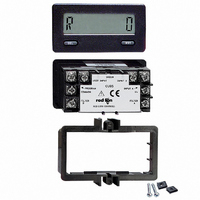
INSTALLATION
when properly installed. The units are intended to be mounted
into an enclosed panel. The viewing window and reset button are
factory sealed for a wash down environment. A sponge rubber
gasket and mounting clip are provided for sealing the unit in the
panel cut-out.
1. Cut panel opening to specified dimensions. Remove
2. Carefully remove the center section of the gasket and
3. Assemble nut fastener and mounting screw onto both
4. Install CUB5 unit through the panel cut-out until front
5. Slide the mounting clip over the rear of the unit until the mounting clip is
6. Alternately tighten each screw to ensure uniform gasket pressure. Visually
7. If gasket is not adequately compressed, and mounting screws can no
INSTALLATION ENVIRONMENT
temperature and provides good air circulation. Placing the unit near devices that generate
excessive heat should be avoided.
of the bezel. Do not use tools of any kind (screwdrivers, pens, pencils, etc.) to operate the keypad
of the unit.
The CUB5 meets NEMA 4X/IP65 requirements for indoor use,
The following procedure assures proper installation:
burrs and clean around panel opening.
discard. Slide the panel gasket over the rear of the unit
to the back of the bezel.
sides of mounting clip. Tip of screw should not project
from hole in mounting clip.
bezel flange contacts the panel-mounted gasket.
against the back of the panel. The mounting clip has latching features
which engage into mating features on the CUB5 housing.
inspect the front panel gasket. The gasket should be compressed about 75
to 80% of its original thickness (recommended torque is 28 to 36 in-oz.).
If not, gradually turn mounting screws to further compress gasket.
longer be turned, loosen mounting screws and check that mounting clip is
latched as close as possible to panel.
Repeat the procedure for tightening mounting screws.
The unit should be installed in a location that does not exceed the maximum operating
The bezel should be cleaned only with a soft cloth and neutral soap product.
Do NOT use solvents. Continuous exposure to direct sunlight may accelerate the aging process
6
WIRING CONNECTIONS
the back of the unit. All conductors should meet voltage and current ratings
for each terminal. Also cabling should conform to appropriate standards of
good installation, local codes and regulations. It is recommended that power
supplied to the unit (AC or DC) be protected by a fuse or circuit breaker.
When wiring the unit, use the label to identify the wire position with the
proper function. Strip the wire, leaving approximately 1/4" bare wire exposed
(strand wire should be tinned with solder). Insert the wire into the screw-
clamp terminal and tighten the screw until the wire is clamped tightly. Each
terminal can accept up to two # 14 AWG wires.
The electrical connections are made with screw-clamp terminals located on