DMS-30PC-4/20S-24RS-I-C Murata Power Solutions Inc, DMS-30PC-4/20S-24RS-I-C Datasheet - Page 2
DMS-30PC-4/20S-24RS-I-C
Manufacturer Part Number
DMS-30PC-4/20S-24RS-I-C
Description
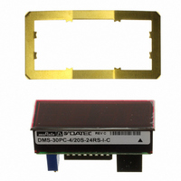
DPM LED 24V SUPPLY 3.5DIG RED
Manufacturer
Murata Power Solutions Inc
Series
DMS-30PC-4/20Sr
Type
Process Meter (4-20mA Loop)r
Datasheet
1.DMS-30PC-420S-24RS-I-C.pdf
(4 pages)
Specifications of DMS-30PC-4/20S-24RS-I-C
Display Type
LED
Measuring Range
4-20mA Loop
Display Style
Red Characters, Black Background
Display Face Size
2.09" L x 0.84" W (53.1 x 21.3mm)
Display Digits
3.5
Display Digits - Height
0.560" (14.22mm)
Backlight
Without
Mounting Type
Panel Mount
Termination
Terminal Block
Voltage - Supply
21.6 ~ 26.4VDC
Input
4 mA to 20 mA
Mounting Style
Panel
Number Of Outputs
1
Lead Free Status / RoHS Status
Lead free / RoHS Compliant
Lead Free Status / RoHS Status
Lead free / RoHS Compliant, Lead free / RoHS Compliant
Other names
811-1080
Available stocks
Company
Part Number
Manufacturer
Quantity
Price
Company:

Part Number:
DMS-30PC-4/20S-24RS-I-C
Manufacturer:
Murata Power Solutions Inc
Quantity:
135


➀ Input Grounding: Except for the "-I"suffi x models which feature isolated current
Performance/Functional Specifi cations
Typical at T
Current Loop Input
Full Scale Input Range
Input Impedence
Voltage Drop
Overcurrent Protection
Performance
Sampling Rate
Accuracy (1 minute warm-up)
Temperature Drift
Power Supply Requirements
DMS-30PC-4/20S-5RS
DMS-30PC-4/20S-5GS
DMS-30PC-4/20S-5RH
DMS-30PC-4/20S-5RL
DMS-30PC-4/20S-24RL
DMS-30PC-4/20S-24XX-I (models)
Display
Display Type and Size
Polarity Indication
Overrange Indication
Physical/Environmental
Operating Temperature
Storage Temperature
Humidity (non-condensing)
Case Material
Weight
loop inputs, all other DMS-30PC-4/20S meters are supplied with their 4-20mA
negative-input terminals (TB1-2, "-") internally connected to their power supply
ground terminal (TB2-2, “-V”). This single-ended input confi guration is compatible
with most grounded-referenced 4-20mA transmitters.
Applications in which the DMS-30PC-4/20S and its associated 4-20mA
transmitter are connected to a common ground and the transmitter drives two or
more loads (for example, the meter in series with a PLC) must have the meter
connected as the fi rst device in the current loop, that is, closest to the system
ground (see Figure 2). If this is not possible and/or the meter must be connected
in the middle of the current loop, then'-I' suffi x models must be used to provide
the required isolation between the meter’s current loop input and the power sup-
ply ground ("-V"). See Figures 2, 3, 4, and 5 for typical loop connections.
A
= +25°C, unless otherwise noted.
Min.
+4.75 to +5.25Vdc at 225mA max.
+4.75 to +5.25Vdc at 225mA max.
+4.75 to +5.25Vdc at 225mA max.
+4.75 to +5.25Vdc at 20mA max.
+7.5 to +32Vdc at 30mA max.
+21.6 to +26.4Vdc at 60mA max.
+3.5
–40
–
–
–
–
0
0
3½ digit, 0.56"/14.2mm high LED
"–1_ _ _ " for negative inputs
"1_ _ _ " for positive inputs
"–" for negative readings
2.5 reading per second
±0.05%FS ±1 Count
1 ounces (28 grams)
±0.15
±0.15
Typ.
100
Polycarbonate
–
–
–
–
–
Max.
±0.3
±0.3
+22
+60
+75
2.0
95
–
www.murata-ps.com/dpm
Cnts/°C
Units
Ohms
Volts
mA
mA
°C
°C
%
DIP-Switch Settings Table
➁ When looking up DIP-switch settings in the Table and the desired display read-
OPERATING AND SETUP INSTRUCTIONS
As shipped, the DMS-30PC-4/20S is factory calibrated to read "000"
for a 4mA input and "1999" for a 20mA input. The following worst-case
procedure assumes the DMS-30PC-4/20S is completely mis-adjusted,
i.e., both potentiometers and the DIP switches are randomly set.
1. Set R7 (gain/span adjust) and R3 (zero/offset adjust) fully clockwise,
2. Set SW1 to ON (up position). See DIP switch setting #3.
3. Apply a precision 4mA input, with proper polarity, and adjust R3 until
4. Apply a precision 20mA and adjust R7 until the display reads "1999".
5. If desired, select the appropriate decimal point by setting either SW5,
Display Reading
1.
2.
3.
4.
5.
6.
7.
Ordering Information
DMS-30PC-4/20S-5RS-C
DMS-30PC-4/20S-5GS-C
DMS-30PC-4/20S-5RL-C
DMS-30PC-4/20S-5RH-C
DMS-30PC-4/20S-24RL-C
DMS-30PC-4/20S-24RS-
DMS-30PC-4/20S-24RH-
DMS-30PC-4/20S-24BS-
DMS-30PC-4/20S-24GS-
ACCESSORIES
DMS-BZL1-C
DMS-BZL2-C
DMS-30-CP
A panel-mount retaining clip is supplied with each model.
ings happen to fall between two switch settings, try performing the adjustments
with both settings to determine which one offers the better settability. Please
keep in mind that the DMS-30PC meter (from which the DMS-30PC-4/20S is
derived) has an accuracy specifi cation of ±2 counts (max.). Thus, it may not
always be possible to obtain the exact desired display reading.
roughly 20 turns, and place SW1-SW8 to OFF (down position).
the meter's display reads "000".
Repeat 3 and 4 to make sure adjustments do not affect one another.
SW6 or SW7 to ON (DP1, DP2 or DP3 respectively).
NOTE: If a display reading other than "000" to "1999" is desired,
refer to the DIP-Switch Settings Table for SW1-SW4 settings.
000 to 100-300
000 to 400-600
000 to 700-1999
±100
±200 to ±300
±400 to ±600
±700 to ±1999
4-20mA Input 3½ Digit Panel Meters
24 Mar 2011 MPM_DMS-30PC-420S.B04 Page 2 of 4
I
I
I
I
-C
-C
-C
-C
SW1
DMS-30PC-4/20S
On
Off
On
On
On
On
Off
with Full-Size LED Displays
+5V supply, standard-intensity red LED's
+5V supply, standard-intensity green LED's
+5V supply, low-power red LED's
+5V supply, high-intensity red LED's
+7.5V to +32V supply, low-power red LED's
+24V isolated supply, standard-intensity
red LED’s
+24V isolated supply, high-intensity red LED’s
+24V isolated supply, high-intensity blue LED’s
+24V isolated supply, standard-intensity
green LED’s
Panel-mount bezel assembly
Panel-mount bezel with sealing gasket
Panel cutout punch
➁
SW2
On
On
Off
On
On
Off
Off
email: sales@murata-ps.com
SW3
On
Off
Off
On
Off
Off
Off
SW4
Off
Off
Off
Off
Off
Off
On