ACA5-20RM-3-AC4-RL-C Murata Power Solutions Inc, ACA5-20RM-3-AC4-RL-C Datasheet - Page 3
ACA5-20RM-3-AC4-RL-C
Manufacturer Part Number
ACA5-20RM-3-AC4-RL-C
Description
AMMETER AC 100A 220VAC RED
Manufacturer
Murata Power Solutions Inc
Series
ACA5-20RMr
Type
Ammeterr
Datasheet
1.ACA5-20RM-3-AC3-RL-C.pdf
(5 pages)
Specifications of ACA5-20RM-3-AC4-RL-C
Display Type
LED
Measuring Range
0 ~ 100.0A
Display Style
Red Characters, Black Background
Display Digits
3.5
Display Digits - Height
0.370" (9.40mm)
Backlight
Without
Mounting Type
Panel Mount
Termination
Terminal Block
Voltage - Supply
170 ~ 264VAC
Dimensions
53.34 mm L x 35.56 mm W x 18.54 mm H
Mounting Style
Panel
Primary Voltage Rating
170 V to 264 V
Secondary Current Rating
100 A
Lead Free Status / RoHS Status
Lead free / RoHS Compliant
Display Face Size
-
Lead Free Status / Rohs Status
Lead free / RoHS Compliant
Other names
811-1975


3. Wire Gauges and Fusing: Wires specifi ed in the Functional Specifi ca-
4. AC Supply Polarity and Grounding: The two supply inputs, TB1-A and
5. Connector Torque Ratings: It is important to tighten TB1’s, screw-ter-
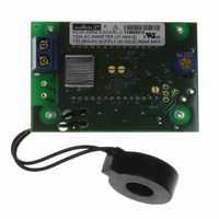
6. Isolation: The built-in toroid sensor (L1) provides a minimum of
tions section must be used for making connections to ACA5-20RM
series ammeters. All power-supply and load wiring must be rated for
the supply voltages and currents they will conduct and must comply
with any code or application-mandated requirements pertaining to the
user’s specifi c installation.
ACA5-20RM ammeters are not internally fused. Terminal block TB1 is
to be used only for powering the ammeter’s internal circuitry; it must
not be used to supply power to external loads. The supply wires feed-
ing these ammeters must be fused with a 0.25A/250V time delay/time
lag fuse, in accordance with applicable regulatory codes.
Wire insulation must be stripped to within ±10% of the stated dimen-
sions, and wires should be inserted into TB1 such that their insulation
is not pinched by the screw terminal.
TB1-B, on ACA5-20RM ammeters are not in themselves polarity sensi-
tive, that is, they have no internal “AC LO” or “AC HI” designations.
ACA5-20RM ammeters do not include or require a connection to earth/
chassis ground.
minals to their rated torque specifi cation of 3.6 pound-inches (0.4Nm).
Proper tightening will minimize connector losses and ensure safe,
reliable operation.
2000Vdc isolation between the external CT’s 5A secondary conductors
and the ammeter supply voltage connected to TB1.
FUSED AC POWER
www.murata-ps.com/dpm
Figure 2. Typical wiring diagram
A
B
TB1
7. CT Precautions: In normal operation, a 5A CT’s secondary circuit
8. CT Connections and Grounding: Some applications require connect-
9. Replacing Analog Panel Meters: ACA5-20RM ammeters can be
BACK VIEW
operates at a very low voltage due to its closed-loop operation and
low burden resistance. However, a CT can still generate potentially
lethal voltages if its output current is suddenly interrupted. For
example, loose 5A CT secondary connections can cause a condition
referred to as “inductive kick”. Inductive kick can generate extremely
high voltages across a CT’s intermittent secondary connections.
Therefore, implementing connections to any 5A current transformer’s
output leads must only be performed with zero load-current fl owing
the CT’s primary load-circuit.
ing one of the external 5A CT’s output leads to earth/chassis ground.
In the USA, consult the latest revision of the National Electrical Code
(NEC) for more information regarding CT grounding.
After all mechanical assembly is completed, connect the two output
leads of the external 5A CT to each other after they are run through
L1’s center hole. Pressure-style connectors (commonly referred to as
“wire nuts”) are acceptable as long as they are rated for the number
of conductors and voltage involved.
used as direct replacements for most analog panel meters driven by
external 5A CT’s. All wiring operations must be performed with both
the load and the supply power sources completely de-energized.
L1
True-rms-AC Ammeters with 5A CT Inputs
ACA5-20RM Series
26 Jan 2011 MPM_ACA5-20RM.A04 Page 3 of 5
email: sales@murata-ps.com